Joint Move
| Description |
The Joint Move works in a similar way to Move to command, but it supports Motion Profiles. The command creates a movement from point A to point B that is optimal for the robot. The movement may not be a direct line between A and B, but optimal for the start position of the joints and the end position of the joints. Joint Move makes movements that are calculated in the robot arm joint space. Joints are controlled to finish their movements at the same time. This movement type results in a curved path for the tool to follow.
|
|
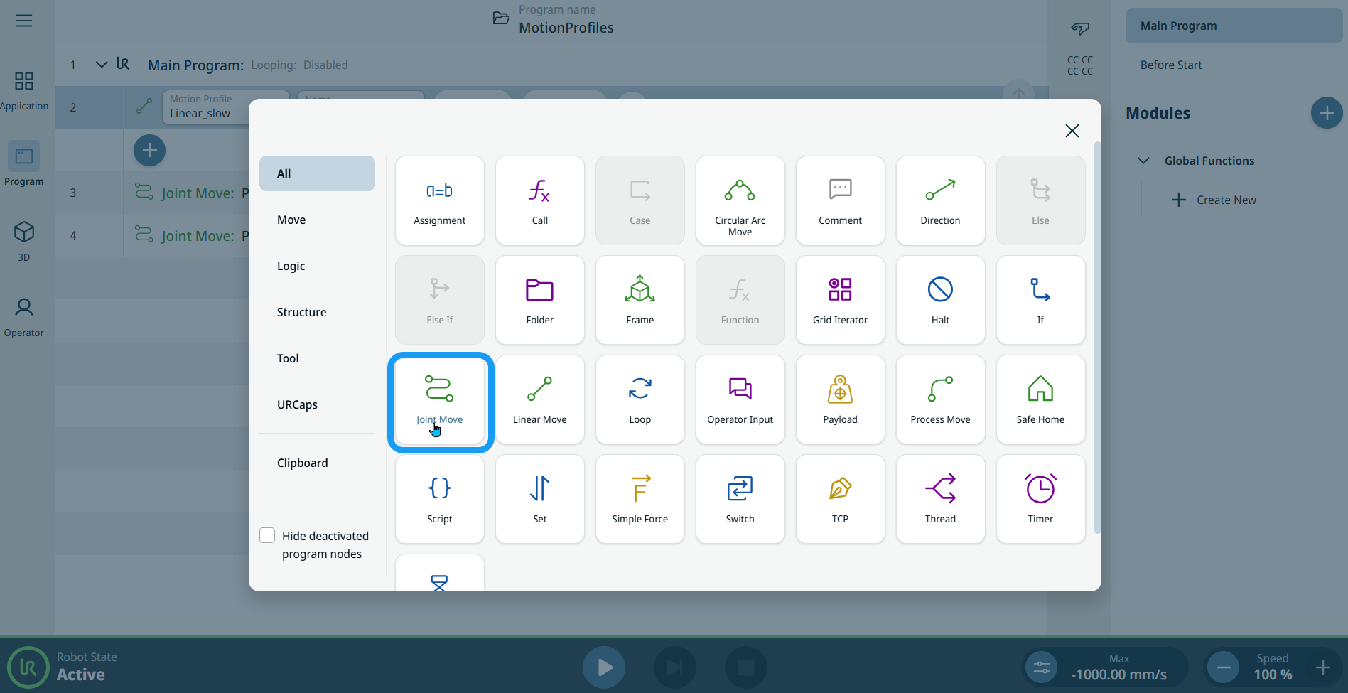
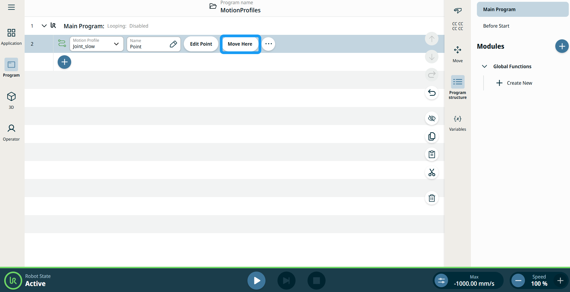
To access Joint Move command |
|
|
|
|
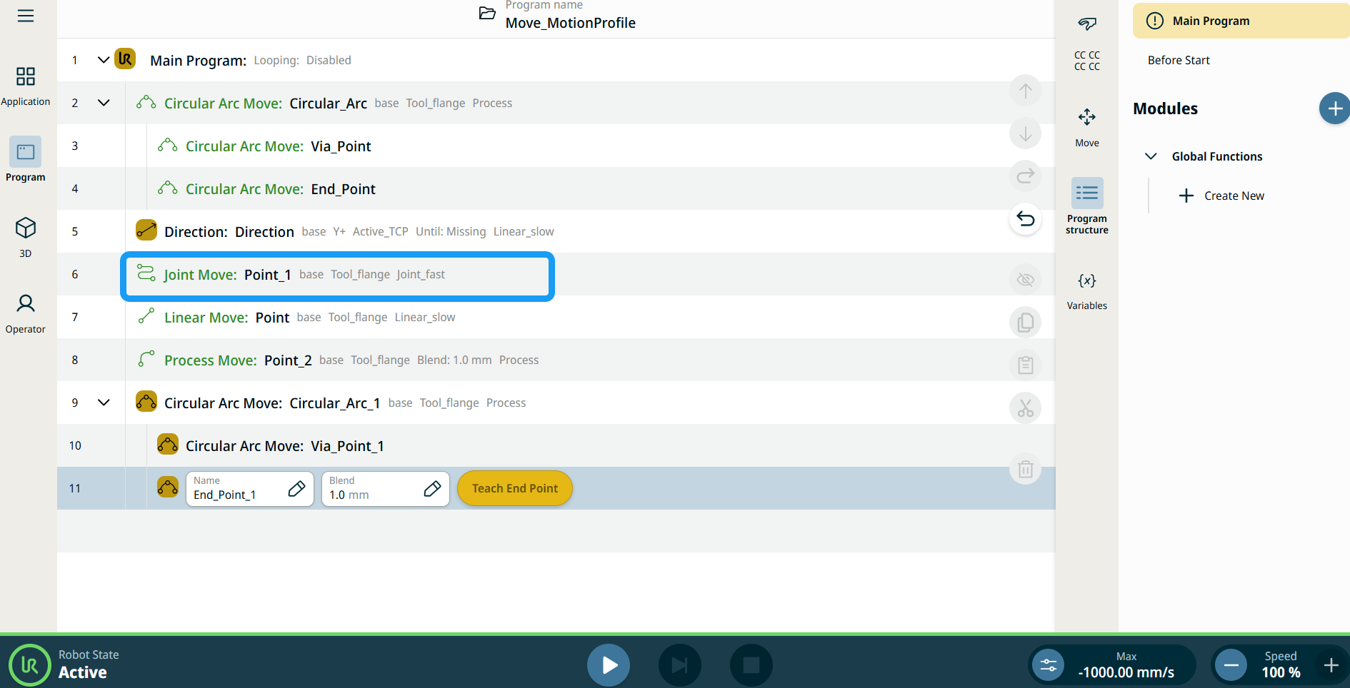
| Motion Profile labels on Move Nodes |
All Move-related command nodes in the program tree display the Motion Profile associated with each node. This feature enables users to see the selected Motion Profile on a Move node. This feature is implemented on the following command nodes: Move nodes with Custom motion profile will display the values for the speed and acceleration instead of Motion profile. |
|
|
|
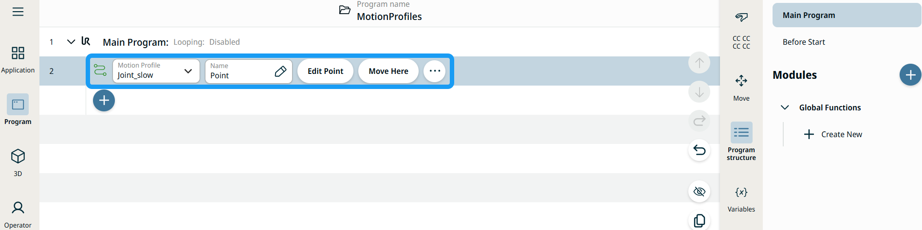
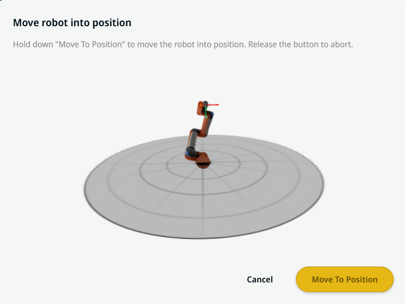
| Using the Move Here button |
The Move Here button is seen in Linear Move and Joint Move commands. This feature enables you to move to the position of a waypoint directly from the program tree. Pressing the Move Here button opens the Move robot into position dialog. The button is visible when the waypoint has been taught and is only enabled when the robot status is in Normal or Reduced mode.
|
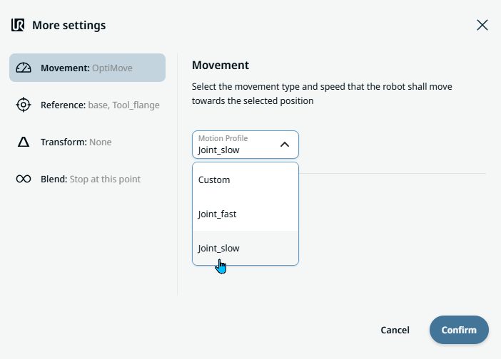
| Movement setting |
|
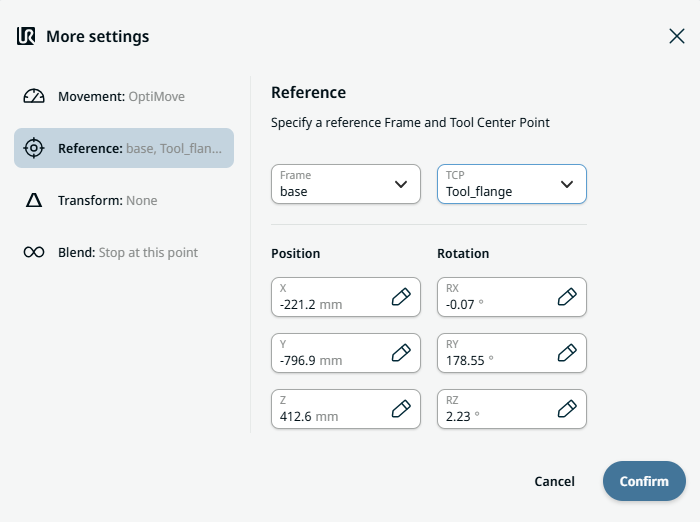
| Reference setting |
|
| Transform setting |
|
|
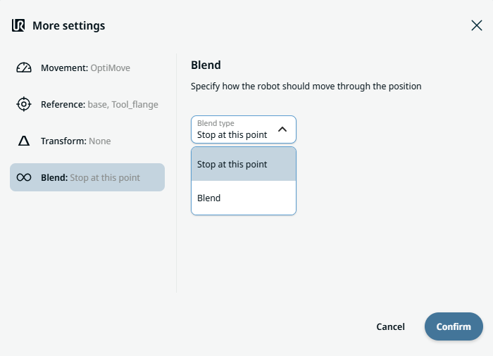
Blend setting |
|