Safety Planes
| Description |
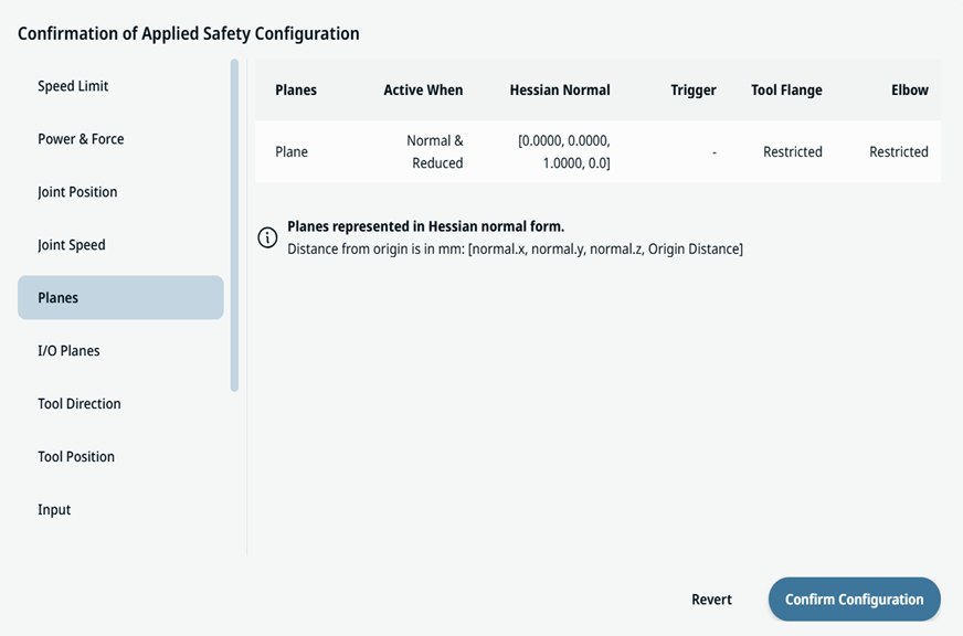
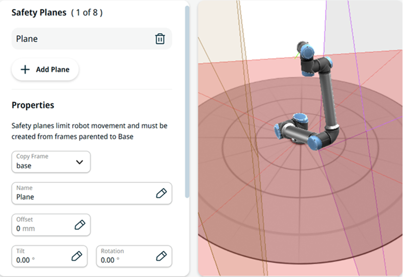
Safety planes restrict the robot workspace, the tool, and the elbow.
|
|
Defining safety planes only limits the defined tool spheres and elbow, not the overall limit for the robot arm. Defining safety planes does not guarantee that other parts of the robot arm will obey this type of restriction. |
| Configuring a Safety Plane |
You can configure safety planes with the properties listed below:
You can configure each plane with the restrictions listed below:
|
| Elbow Joint Restriction |
The feature is enabled by default. You can enable Restrict Elbow to prevent the robot elbow joint from passing through any of your defined planes. Disable Restrict Elbow to allow the elbow to pass through planes.
|
| Tool flange and wrist joint restriction |
Restricting tool flange and wrist joints prevents the tool flange and wrist joints from crossing a safety plane. The tool flange and wrist joints are monitored by the safety system, preventing them from crossing a safety plane. Disabling the restriction can be useful if it is exclusively the attached tool that should be monitored, e.g. in welding applications where only the welding tool is dangerous and the robot moves at low speeds. Safety planes are defined in relation to a frame defined in the installation or the robot world frame. The robot is allowed to move such that all monitored parts of the robot arm and user defined safety spheres are in front of the plane.
|
Create Safety Plane Using a Frame
| Description |
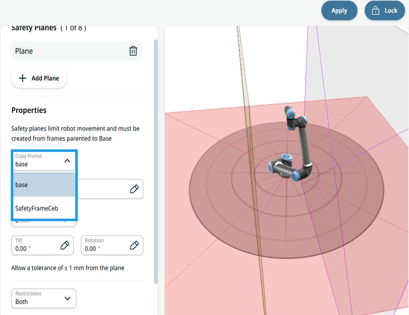
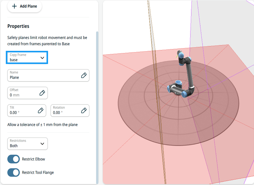
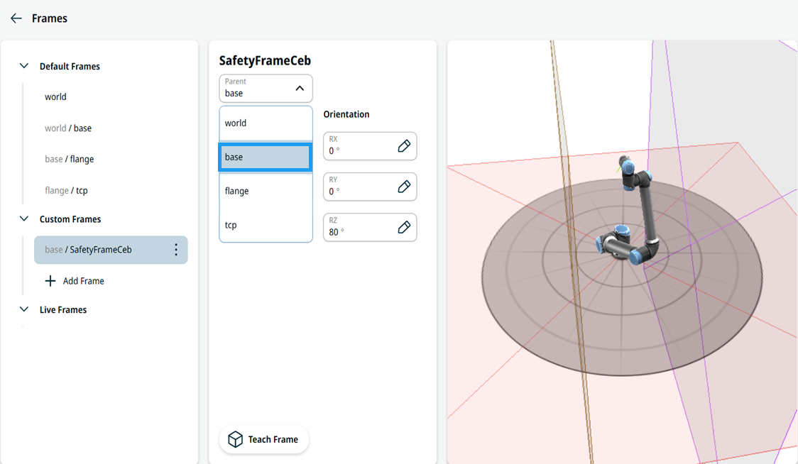
You can use an existing frame to define a safety plane. This provides a more intuitive way to specify plane parameters from a predefined position and rotation (X, Y, Z, RX, RY, RZ). Select the frame in the Copy Frame drop-down menu.
The Copy Frame drop-down menu is found in the parameters of a safety plane definition on the Planes screen. This list includes frames defined on the Frames screen. When you select a frame, it is used as the safety plane definition. If you specify offset, tilt, and rotation parameters, they are applied to the selected frame (see "Configuring a Safety Plane"). The resulting safety plane combines all parameters.
|
|
|
See the "Frames" section in Software Handbook. |
||
|
Creating Safety Planes using Frames |
|
||
|
|
Selecting Reference Frame in Safety Plane |
|
||
|
|
|
||
|
|
A frame used for a safety plane may be inverted from what you expect. If the robot is positioned on the violating side of the plane, add a tilt of 180 degrees. For restrictions on plane configurations, elbow joint restriction, and tool flange restriction, see "Safety Planes".
|