Connecting Robot Arm to Control Box (CB7)

Description

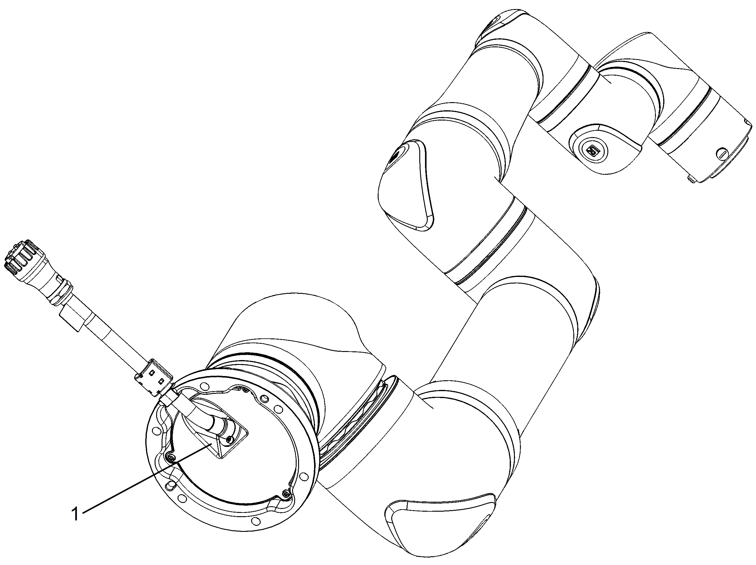
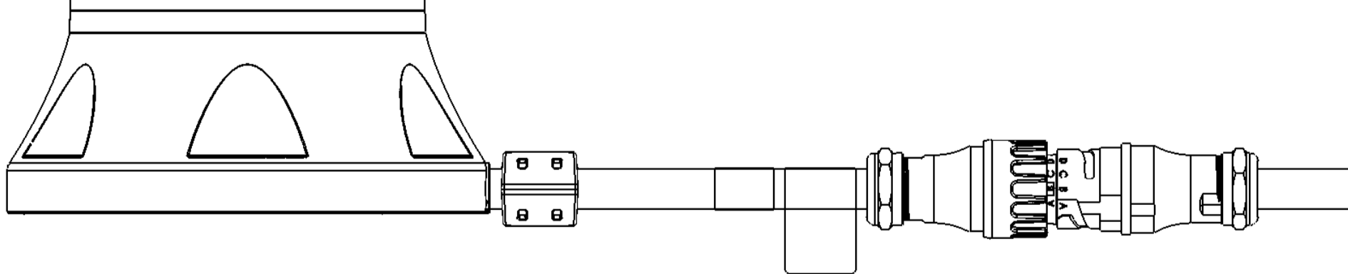
Connecting the robot arm to the Control Box establishes power, communication, and safety functions required for robot operation. The robot power and communication cable connects and exits directly through the bottom plate of the robot base, called a bottom-mounted cable exit, rather than exiting horizontally from the side.

Bottom-mounted cable exit


Ensure all connections are correct before you power on the system.


Improper robot connection can result in loss of power to the robot arm.

  • Do not disconnect the Robot Cable when the robot arm is turned on.

  • Do not modify the original Robot Cable.

Incorrect mating or unmating can damage the Harting connector.

  • Do not force the connector if the end-marking letters are not aligned.

  • Do not twist the connector before it is fully seated.

  • Do not pull on the cable to disconnect the connector.

  • Do not rock or tilt the connector during mating or unmating.

Connecting the Base Flange Cable directly to any Control Box can result in equipment or property damage.

  • Do not connect the Base Flange Cable directly to the Control Box.

  • Always use a UR robot cable to connect the Base Flange to your Control Box.

    Use the same mating and unmating steps at the Control Box connector and at the robot Base Flange connector. For the mating and unmating procedure, see Robot Cables (g-Series).

Robot Cable to Control Box

The Robot Cable connects the robot arm to the Control Box.


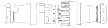
  1. Plug the Robot Cable into the robot cable connector on the Control Box. Align the end-marking letters on both connector ends.

    Robot Cable marking alignment


  2. Twist the connector clockwise to lock it securely.

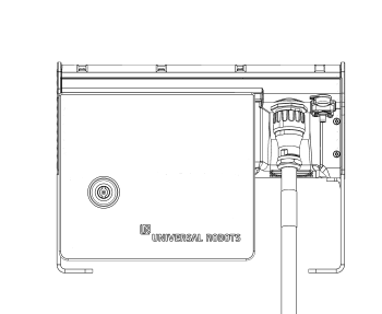
  3. Confirm the connector is fully locked.

    Robot Cable connection to Control Box


Robot Cable to Base Flange Connector

Connect the Robot Cable to the Base Flange Connector to prepare the robot system for operation.


Robot Cable connection to Robot Arm


  1. Align the pins using the end-marking letters on both connector ends.

  2. Insert and twist the connector clockwise to lock it securely.