
MINIMIZE COORDINATE DIFFERENCE
This describes strategies to minimize coordinate differences when programing applications.
Created: December 6th, 2024.
New features introduced in Polyscope 5.16 added URScript functionalities that allow treating frames as objects. This enables the relocation of frames to new poses and referencing of frames to other frames. These features allow for corrections over setups that have been modified and enable recalibrating the entire program in case of a loss of precision.
Some case examples are presented below to illustrate the possibilities of using these features:
Case 1: Trajectory Referenced from a Custom Frame
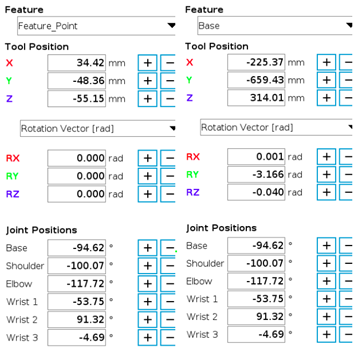
Teaching and using frames of reference, features, closer to the path points reduces deviation since there is less distance involved. The image bellow compares relative position against custom feature and base feature, while the robot is in the same position, same joint values. Using custom frames help to reduce relative errors in non-calibrated robots.
Examples:
- Module 10 : Module 10 ELearning explains and guides over the use of custom frames to reference points.
Case 2: fast reconfiguration of Trajectory Referenced to A Frame
By creating a new frame (e.g., table) using the add_frame(name, pose, ref_frame="base") function, and creating points as frames referencing and attaching them using attach_frame() (e.g., cornerA, cornerB) to the first frame (table), whose pose can be referenced to either the robot's base frame or the world frame, we can easily update the program's motion. This is achieved by simply reteaching the frame's position, move_frame(name, pose, ref_name), relative to its parent frame (world or base) if the robot's position has changed or the trajectory has shifted due to changes in the work environment, such as the table being moved by a general offset.
This also provides a method to reduce deviations from the trajectory in non-calibrated robots. Teaching and using a frame of reference close to the path points reduces deviation since there is less distance involved.
Examples:
- Module 10 : Module 10 ELearning
Case 3: Use of Fiducial Markers to Enhance Precision
Fiducial markers are tools used in the electronics industry to reconfigure trajectories and avoid deviations in component placements. A similar strategy can be applied using fixed points in a robot application setup. A program with a 2D or 3D trajectory can reference a specific point, such as the midpoint of two, or more, fiducial markers, to improve precision. That point can be located by interpolation. For this approach, the interpolate_pose() function is used.
Steps:
- Set two, or more, physical points to act as fiducial markers over the work set up or the item to work upon.
add_frame(markerA, pose, ref_frame="base")
add_frame(markerB, pose, ref_frame="base")
These two points might have a physical fixed reference on the work environment. - Define a reference point relative to these fiducial markers to set the reference frame for all the other points, and to be checked at the beginning of the program, e.g. corner of the piece or work environment.
add_frame(referenceFrame, pose, ref_frame="base") - Every time the program starts, if the verification of the reference point fails, use the interpolation function to adjust the frame based on the physical fiducial markers:
referenceFramePos = interpolate_pose(markerA,markerB, i)
move_frame(referenceFrame, referenceFramePose, ref_name = "base")
i is the index that indicate the position of the referenceFrame along the line from markerA and markerB, this should be determine at the planification of the application. More than two markers are necessary for points that lies outside of the segment markerA-makerB or in 3D space. Check Interpolate a square or lattice using scripts.