
3-position Enabling Device and Mode Selector- connection and configuration for CB3 and e-Series
Requirements
To use a mode selector and a 3-Position Enabling Device (3PED) with UR-Controller, the controller has to comply with the following requirements:
CB3 Software version: 3.2.18654 or higher
e-Series Software version: All version
Revision of the Safety Control Board (SCB)
- Safety A: 473 or higher
- Safety B: 212 or higher
Note that older or newer software versions may behave differently.
Software version and revision of the processors on the Safety Control Board are shown on the “About”-window in PolyScope.
Remark:
The revision of the safety processor are shown only from Software revision 3.2.18654 and higher.
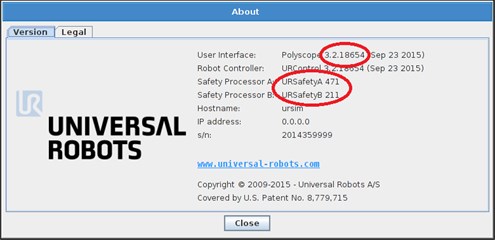
Fig. 1‑1: About-window in Polyscope
If the requirement of the software revision is not met, the robot can be updated to a newer software version as described in the service manual and support site.
If the requirements of the needed revision for the safety processors are not met, the Safety control Board must be replaced with a board containing the required firmware revision.
Safety Control Board with latest revision can be purchased by contacting your local distributor from where the robot has been acquired.
Replacement of board MUST be carried out by instructed personnel to avoid any ESD-issues (ESD = Electro Static Discharge).
1. How to connect Mode Selector and 3-position Enabling Device
Mode selector:
The selector can be a key switch with redundant electrical layout or signals from dedicated safety PLC.
3-position enabling device:
Requirement to a 3-position Enabling Device is a redundant layout and a push button with three positions, where only the position in the middle creates a connection.
Signals must be redundant and connected to two of the configurable inputs in UR control box. Use the 24V terminals on the input connector as indicated on Fig. 2-1.
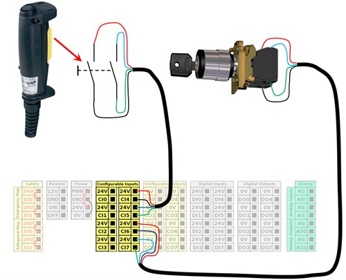
Fig 2‑1: Connection of the Mode Selector and a 3-position Enabling Device
2. Configuration of the safety inputs
To configure the connected safety inputs from Fig 2-1, go to Installation tab and select Safety Settings. The safety settings have to be unlocked by typing in safety password.
Remark:
The safety settings can only be unlocked if a safety password has been set under „Settings/Password“.
Once the safety setting area is unlocked, go to Safety I/O-tab. Here you can select a safety function for each configurable input and output. First select the 3-position enabling device in the dropdown box on the inputs where the 3-position enabling device is connected. (See fig. 3-1)
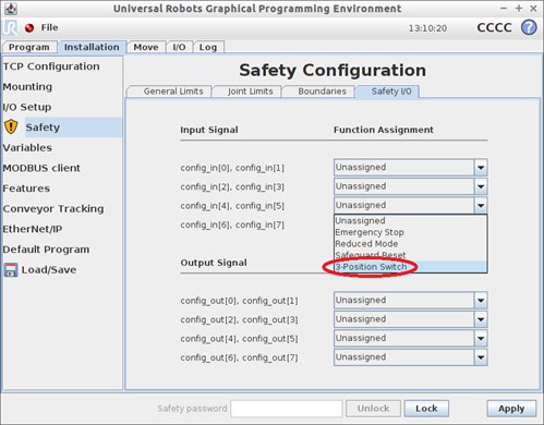
Fig 3‑1: Configuration of 3-position Enabling Device
Once this has been set, it opens up for a new safety function named Operational Mode. Assign this function to the inputs where the Mode Selector switch is connected (see fig 3-2)
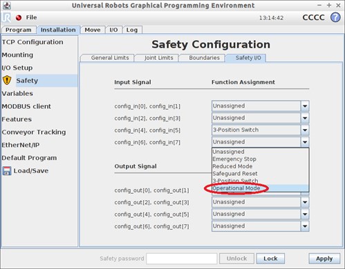
Fig 3‑2: Configuration of Mode Selector
3. Operation
If the Mode Selector and 3-position Enabling Device is connected and configured correct, the following modes can be selected by using the Mode Selector:
- Running mode
- Programming mode
![]() Running mode:
Running mode:
On PolyScope Welcome-screen, the button “Program Robot“ will be disabled in Running mode. Only “Run Program” can be accessed by the operator in Running mode. (see fig. 4-1). Robot cannot be manually jogged by the operator in Running mode.
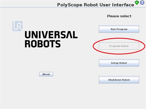
Fig 4‑1: PolyScope Welcome-screen in Running mode
![]() Programming mode:
Programming mode:
To access “Program Robot”, switch the Mode Selector from Running mode to Programming mode. The “Program Robot button then becomes accessible.
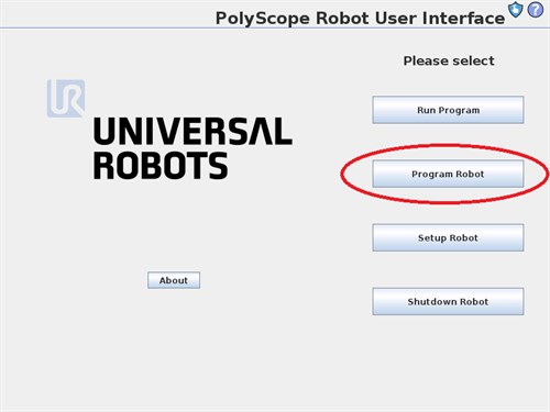
Fig 4‑2: PolyScope Welcome-screen in Programming mode
In programming mode the robot is by default safeguarded and cannot be controlled by the operator. In order to jog the robot, it is required to press and hold the 3-position enabling device in neutral (middle) position while jogging the robot. This is called Normal mode.
Upon releasing or pushing hard on the 3-position enabling device, robot will go into safeguard mode. Visual indication of the state is found in top left corner of the screen.
Yellow indicates safeguarded state:
![]()
Fig 4‑3: Safeguard state
Green indicates normal state:
![]()
Fig 4‑4: Normal state
4. Additional remarks:
Violations:
Allowed delay between two redundant signals is 100ms for software v3.2 and later. In case a violation of this delay occur, a security stop will arise and display a popup (see fig. 5-1)
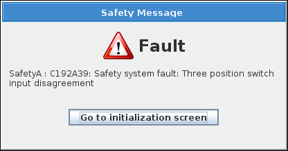
Fig 5‑1: Popup indicating violation of the allowed delay between the redundant signals
Initializing in Programming mode:
- Click “START” to power on robot arm > robot state changes to Safeguard Stop
- Press and hold 3-position enabling device > robot state changes to Idle
- Click “START” while pressing 3-position enabling device to release the brakes > robot state changes to Normal
If 3-position enabling device is not being pressed while releasing the brakes, it will not be possible to release the brakes (see fig. 5-2)
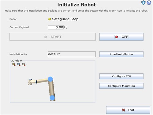
Fig 5‑2: Initializing after StartUp the robot when robot is in programming mode