First Program

Description

Creating your first program in PolyScope X teaches the robot arm to move through a series of waypoints that define the path to follow. An End Effector tool should be attached at the end of the arm.

To configure the tooling at the end of the arm, see End Effectors Application.

To configure the tooling at the end of the arm, see End Effectors Application in the Software Handbook.


To create a simple program

The first program performs the following steps:

  1. Move to position A.

  2. Set an I/O.

  3. Wait for 3 seconds.

  4. Unset the I/O.

  5. Move to position B.

System Manager access

  1. In the main screen, tap the header to open the System Manager.

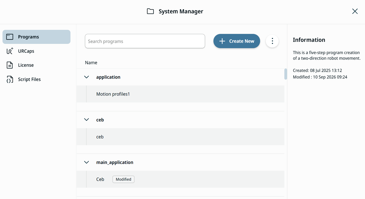
  2. In the Programs tab of the System Manager screen, tap Create New.

    Create New program button of the System Manager
 
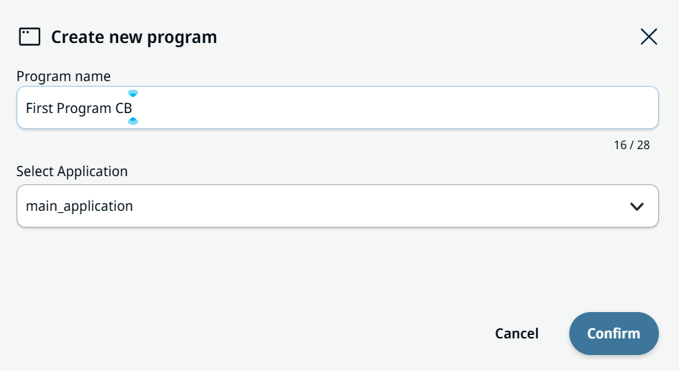
  1. In the Create new program box, fill in the Program name and Select Application fields. Tap Confirm.

    Create new program box with the Program name and Select Application fields

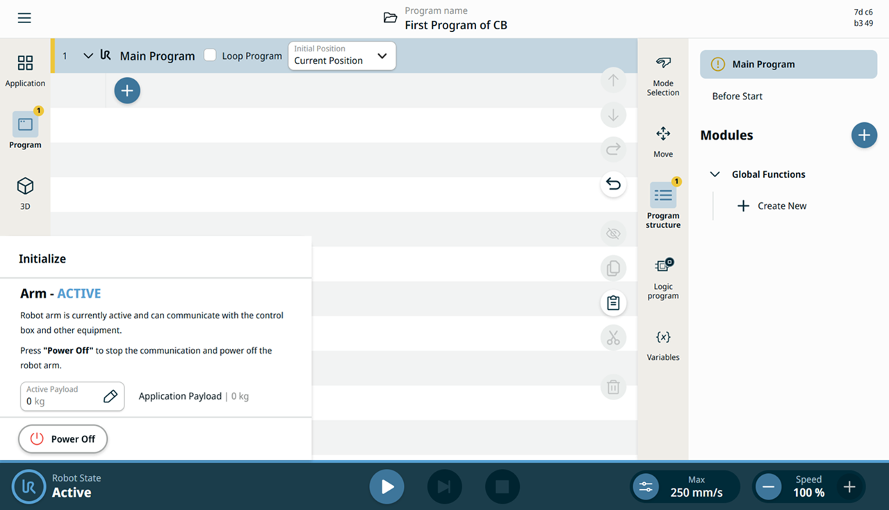
    The main screen now shows your program name. In the multitask screen, the Main Program tab is yellow, indicating that program creation is ready to start.

Initialize Robot
  1. On the left side of the footer, tap Robot State to initialize.


  1. Tap Power On, then Unlock. The robot state changes to Active, and the Play button and the High Speed Manual Mode and Speed sliders become available.

    An Active Robot State and the enabled footer controls
  2. On the main navigation, tap the Program menu icon.

    See Command Nodes.

    See Basic Command Nodes description in the Software Handbook.

First command: Joint Move


Action: move to
Position A

  1. Tap the Joint Move command. In PolyScope X, the Waypoint node is merged into this command.

    See the Joint Move command node description.

    See the Joint Move command node description in the Software Handbook.

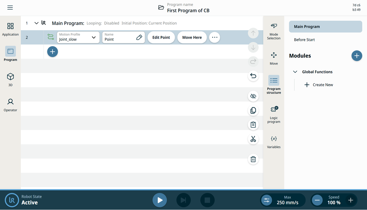
    Joint Move node with the editable fields

    Two editable fields, two buttons, and an ellipsis icon are added to the program tree:

    • Motion Profile

    • Name

    • Edit Point

    • Move Here


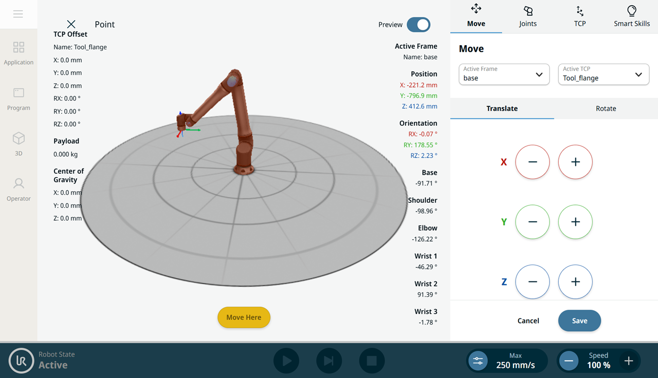
  1. Tap Edit Point. The robot arm appears in 3D, with the Move menu on the right side of the screen.

    Edit Point screen with the robot arm in 3D
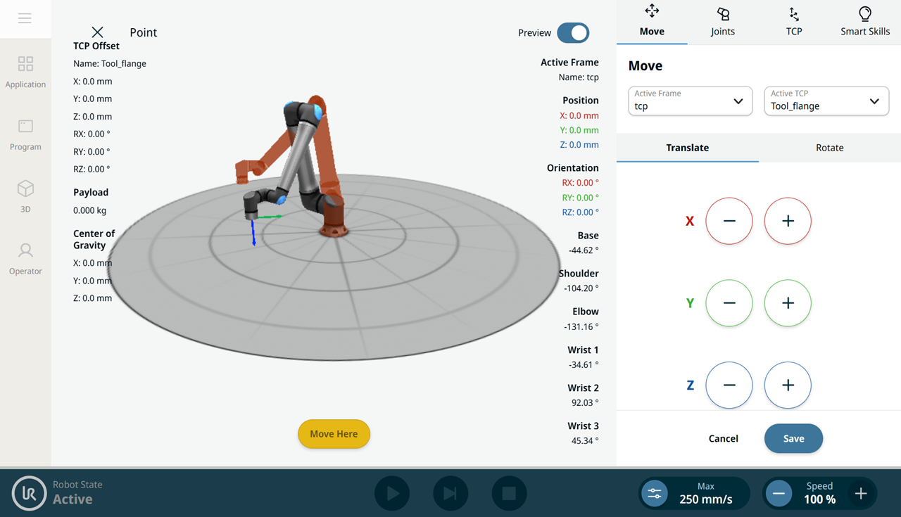
  2. Use the plus-minus buttons of the X, Y, and Z axes to jog the robot to the position of your waypoint, then tap Save.

    Jogged waypoint position in the Move menu

Name the first waypoint

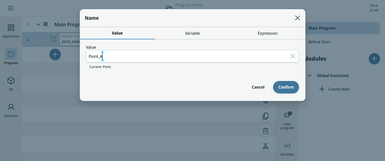
  1. In the Name field, enter Point_A on the Value tab and tap Confirm.

    Name editor with Point_A

Second command: Set


Action: Set an I/O for the end effector

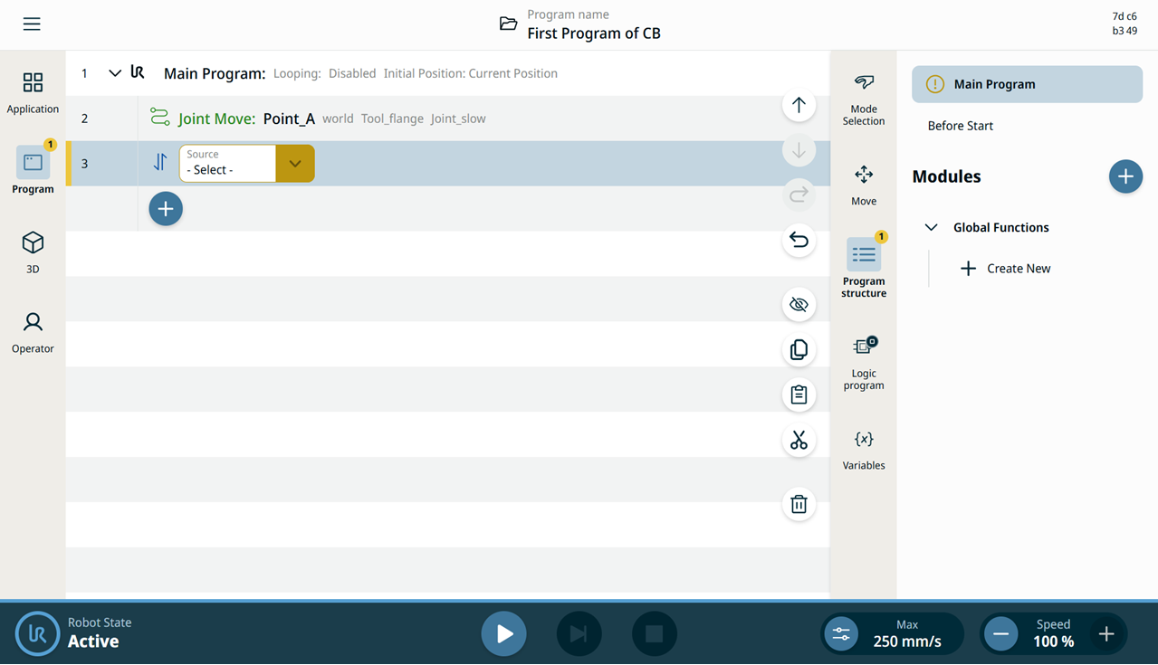
  1. Tap the add icon in the program tree, then tap the Set command icon.

    See Set command node.

    See Set command node description in the Software Handbook.

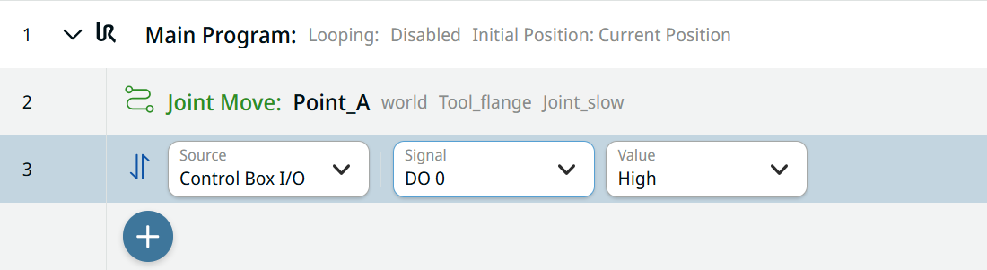
    Set node with the Source field
  2. Tap the Source field and select Control Box I/O.

  3. A Signal field is added. Select DO 0. A Value field is added to the right; select High.

    Set node with the editable fields

Third command: Wait


Action: robot waits for a specified number of seconds

  1. Tap the add icon and choose the Wait command.

    See Wait command node.

    See Wait command node description in the Software Handbook.

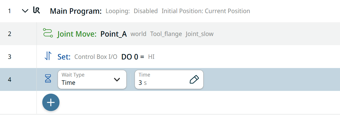
  2. In the Wait Type field, select Time, to make the robot wait for a specified number of seconds.

  3. Tap the Time field, enter 3 (three seconds) on the Value tab, and tap Confirm.

    Wait node with the editable fields

Fourth command: Set


Action: Unset an I/O for the end effector

  1. To create a second Set node, repeat steps 11 to 13.

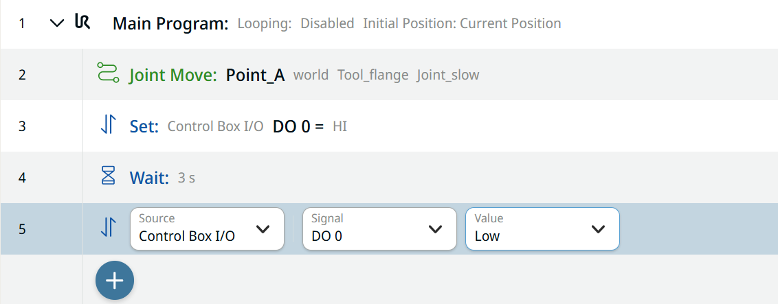
  2. In the Signal field, select DO 0. A Value field is added to the right; select Low.

    Second Set node

Fifth command: Joint Move


Action: move to
Position B

  1. Tap the add icon in the program tree. Repeat steps 7 to 9 to create a second waypoint. Move the robot arm to a position clearly distinguishable from Point_A.

Name the second waypoint

  1. In the Name field, enter Point_B on the Value tab and tap Confirm.

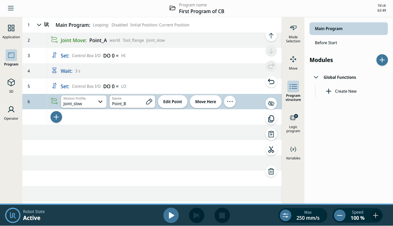
    The main screen shows your first program.

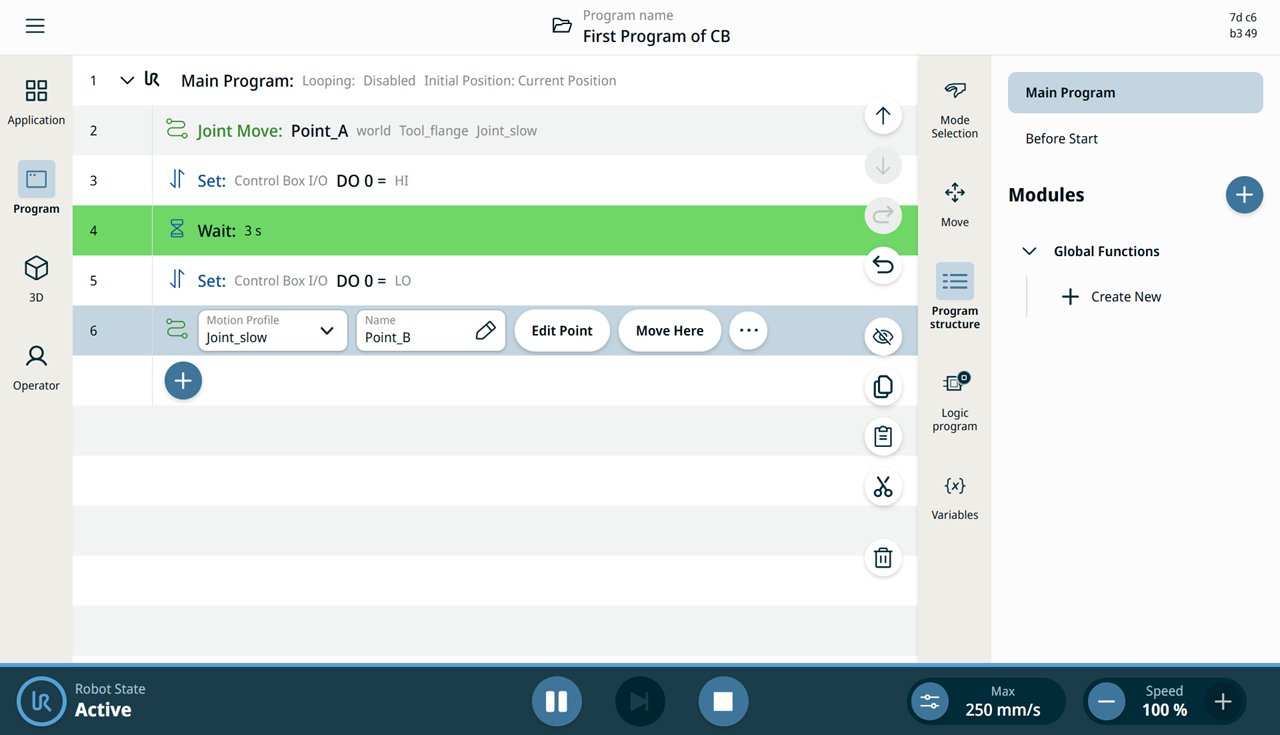
    Completed program tree from Point_A to Point_B

Verify the program in 3D viewer

  1. Tap the 3D Viewer icon on the main navigation.

  2. In the footer, tap the Play button. In the program tree screen, the node highlighted in green is the one currently running.

    Running program with the Wait node highlighted in green


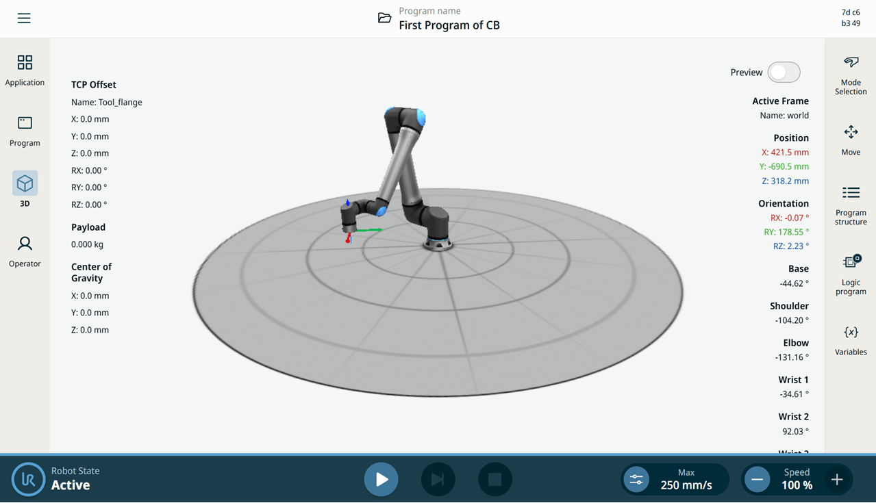
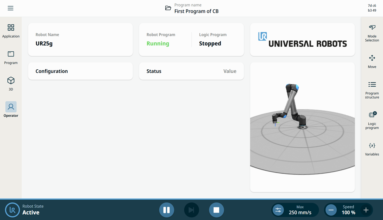
  1. In the 3D Viewer and Operator screens, you see the robot move. Beside the three-dimensional graphics, you see the numerical details of the robot joints, position, and orientation.

    Robot arm in 3D Viewer
    Operator screen with the Robot Program

Verify the program in Communication

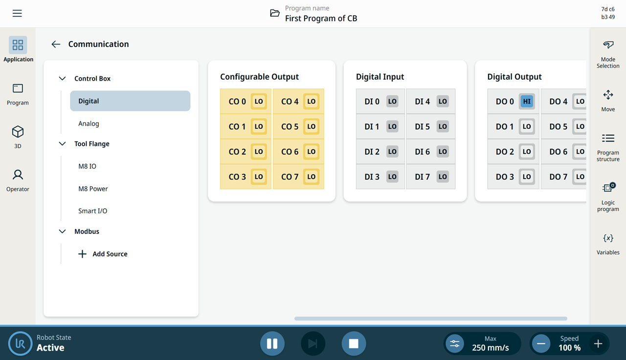
  1. Go to the Application tab and tap the Communication icon. Observe how the state of Digital Output 0 (DO 0) alternates between LOW and HIGH when you tap the Play button in the footer.

    Communication screen with Digital Output DO 0 set to HI

    See Communication tab for more details.

    See Communication tab description in the Software Handbook for more details.