Joint Move

Description

The Joint Move command node supports Motion Profiles. It creates a movement from point A to point B that is optimal for the robot. The path may not be a straight line between A and B; it is optimized for the start and end joint positions. Joint Move calculates movements in joint space. The joints finish their movements at the same time, so the tool follows a curved path.


To access Joint Move command

  1. Go to the main program screen. For command nodes, see Command Nodes.

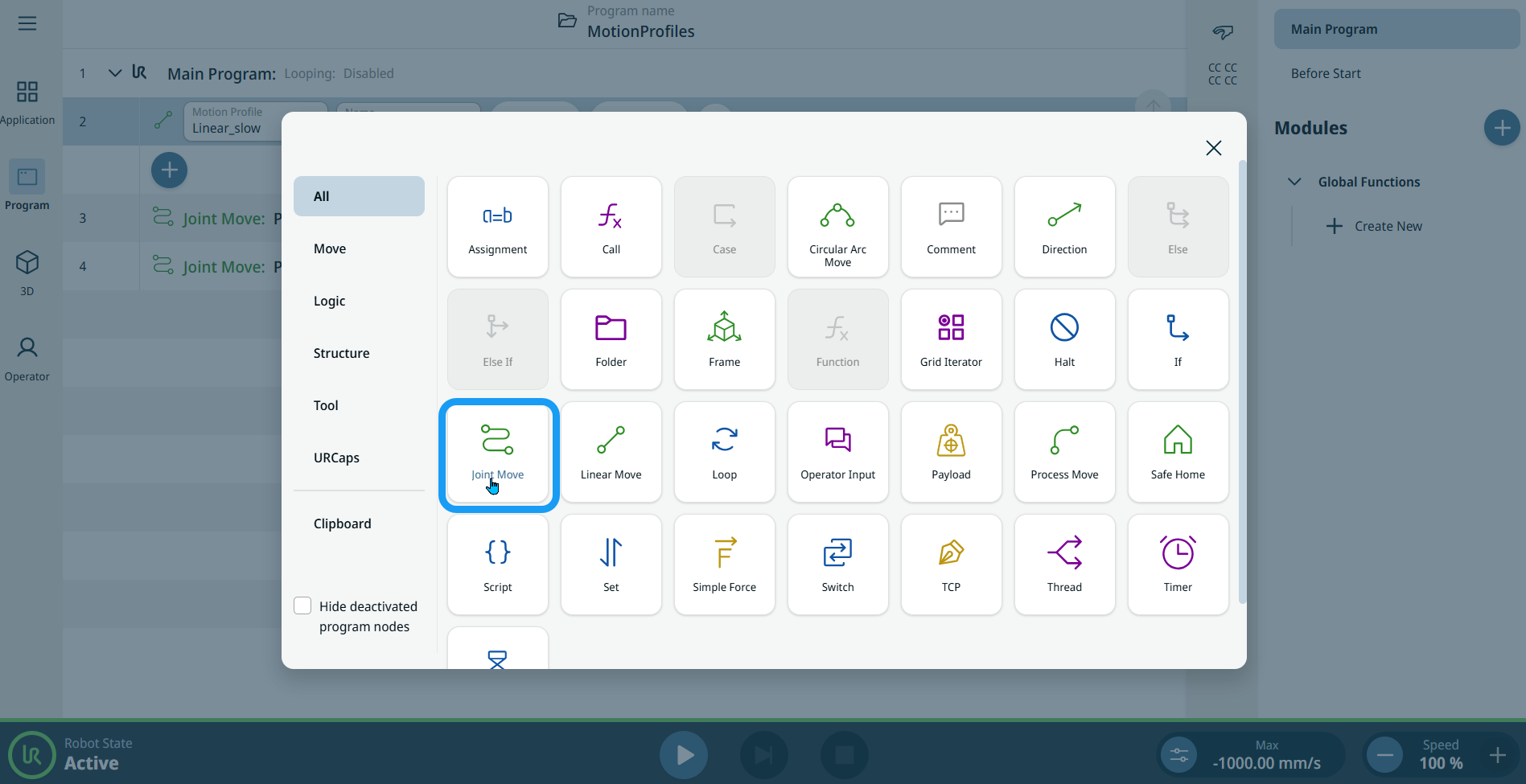
  2. Tap the Joint Move icon in the Commands toolbox.


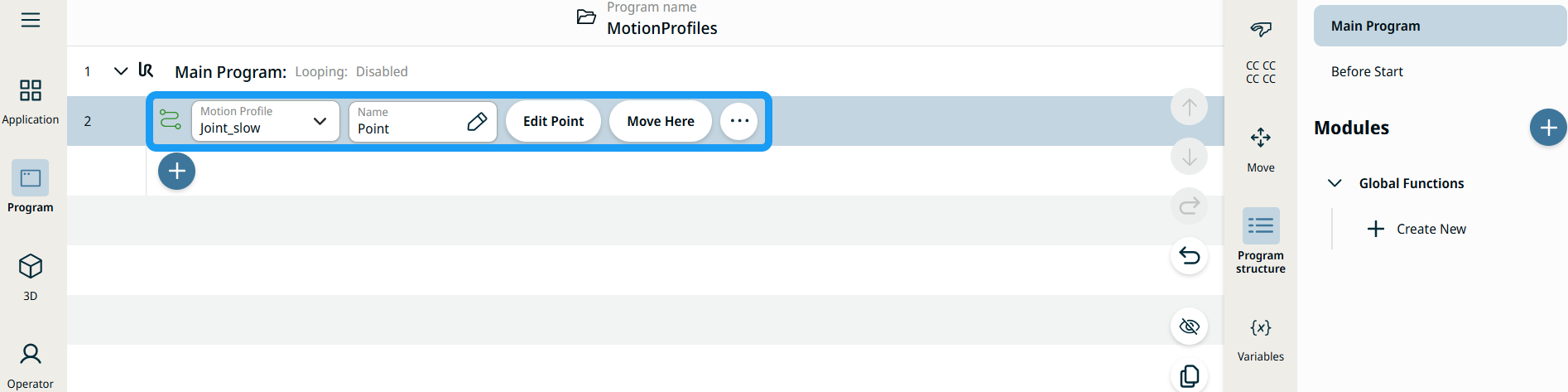
    A node with two editable fields, two buttons, and an ellipsis icon is inserted into the program tree. These are the two editable fields:

    • Motion Profile

    • Name

    These are the two buttons:

    • Edit Point

    • Move Here


  1. Tap the Motion Profile field and select one of these three options:

    • Custom

    • Joint_fast

    • Joint_slow

  2. Tap the Name field, and three tabs appear:

    • Value

    • Variable

    • Expression

  3. Enter the data in the Value, Variable, and Expression tabs, and tap Confirm. For field types, see Value-Variable-Expression Tabs.

  4. Tap Edit Point. A new screen appears with the robot arm interface where you can jog the robot to the desired position.

  5. Tap the More button.

    The More settings screen appears with four settings:

    • Movement

    • Reference

    • Transform

    • Blend


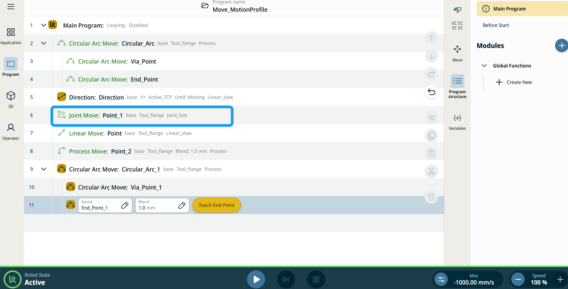
Motion Profile labels on Move Nodes

All Move-related command nodes in the program tree display the Motion Profile associated with each node. This feature enables users to see the selected Motion Profile on a Move node. This feature is implemented on the following command nodes:

Move nodes with Custom motion profile will display the values for the speed and acceleration instead of Motion profile.


Using the Move Here button

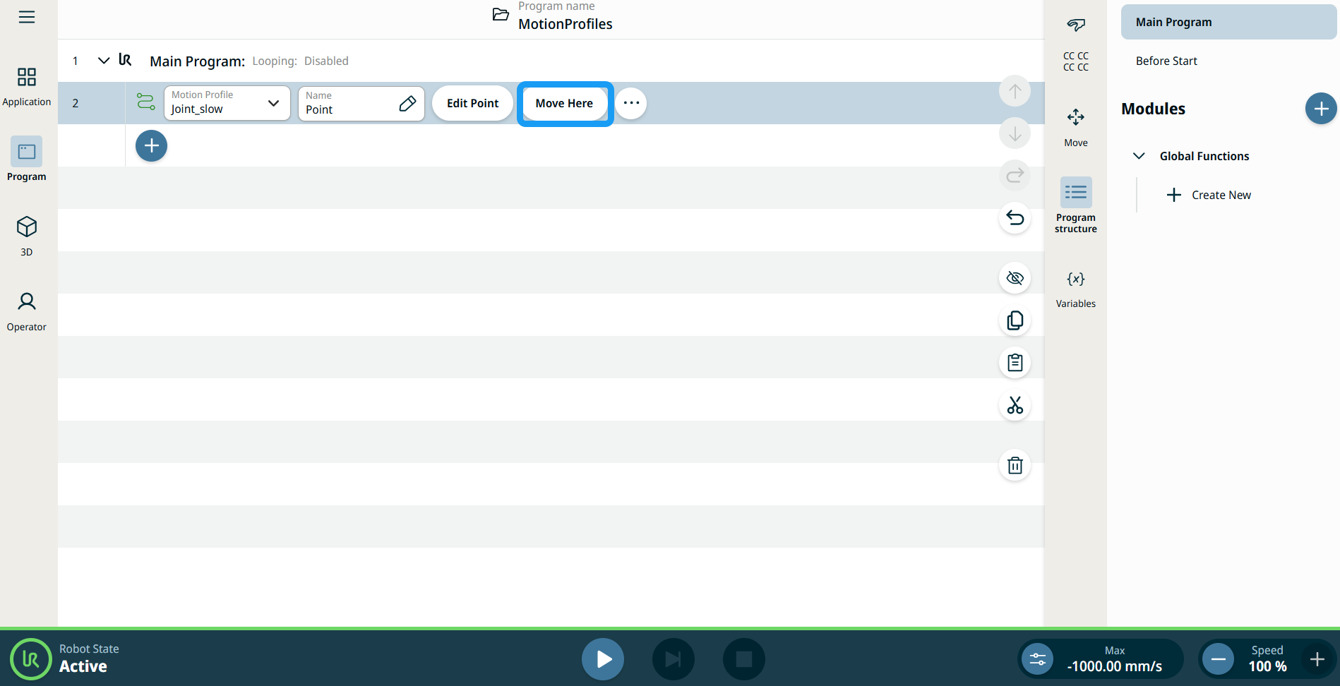
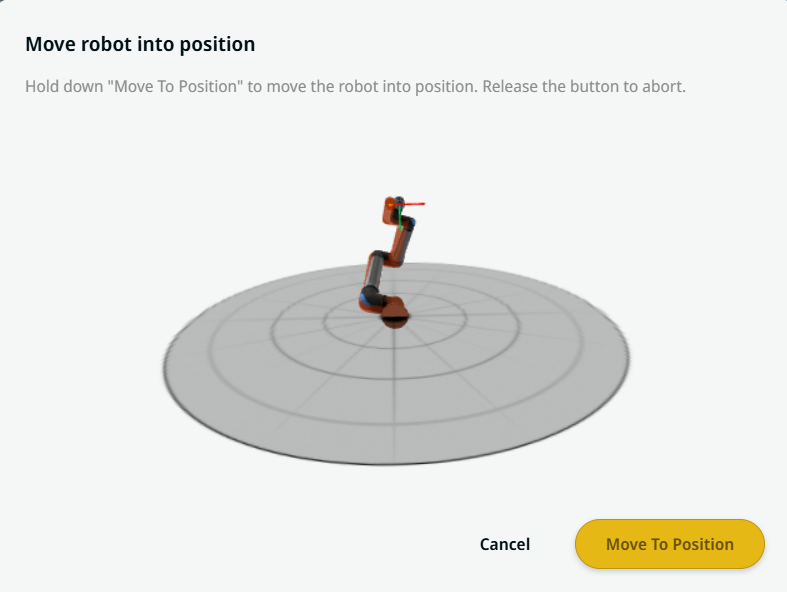
The Move Here button is seen in Linear Move and Joint Move commands. This feature enables you to move to the position of a waypoint directly from the program tree. Pressing the Move Here button opens the Move robot into position dialog. The button is visible when the waypoint has been taught and is only enabled when the robot status is in Normal or Reduced mode.


  1. Tap the add icon to insert the Linear Move and Joint Move in the command tree.

  2. Tap the Edit Point button of the first move node in the command tree, be it Linear Move or Joint Move nodes.

  3. Jog the robot using the plus-minus button in the X, Y, Z coordinates. Tap Save.

  4. In the second move node in the command tree, tap Move Here. A pop-up screen appears to enable Move robot into position. Long tap Move to Position. Tap Ok.


Movement setting
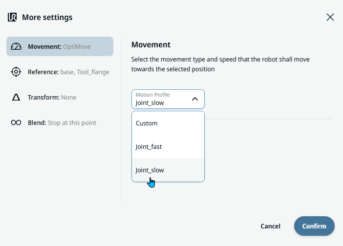
  1. Tap the Movement setting on the left side. A Motion Profile field with the following options appears on the right side. Joint_slow is the default.

    • Custom

    • Joint_fast

    • Joint_slow

  2. If Custom is selected, three more fields appear:

    • Speed Type

    • Speed

    • Acceleration

  3. Choose either OptiMove or Classic when you tap Speed Type.

  4. Tap the Speed field, and the Value, Variable, and Expression tabs pop up.

  5. Enter data in each tab, and tap Confirm. For field types, see Value-Variable-Expression Tabs.

  6. Tap the Acceleration field, and the Value, Variable, and Expression tabs pop up.

  7. Enter data in each tab, and tap Confirm. For field types, see Value-Variable-Expression Tabs.

  8. When Joint_fast and Joint_slow are selected, the OptiMove speed and acceleration are shown.


Reference setting
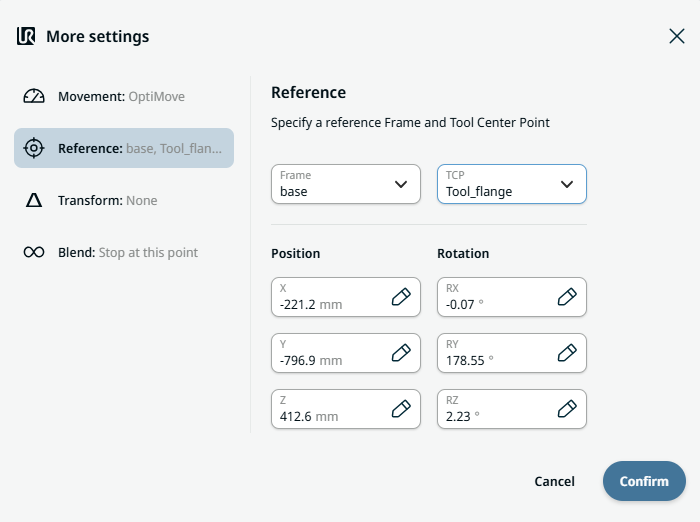
  1. Tap the Reference setting.

  2. Choose either the Frame or TCP field.

    In the Frame field, these five options are available:

    • world

    • base

    • flange

    • tcp

    • view

    In the TCP field, two options are available:

    • Active_TCP

    • Tool_flange

  3. In the Position column, tap the X, Y, Z tabs, enter your chosen value for the robot, and tap Confirm.

  4. In the Rotation column, tap the RX, RY, RZ tabs, enter your chosen value for the robot, and tap Confirm.

    The view frame is available for jogging only. If you select view while you edit a waypoint and then tap Save, the reference reverts to the world frame. You cannot store the view frame as a waypoint reference.


Transform setting
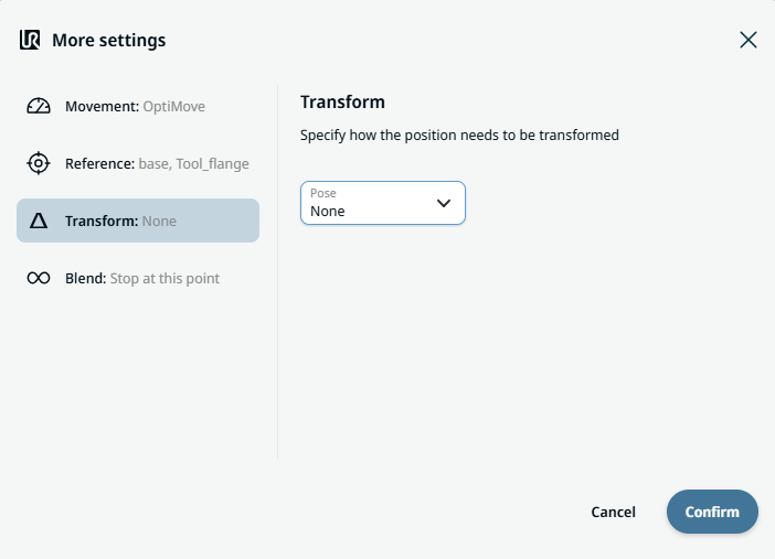
  1. Tap the Transform setting.

  2. Tap the Pose field and tap Confirm.


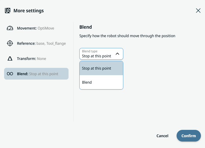
Blend setting

  1. Tap the Blend setting.

    A Blend type field appears with two options:

    • Stop at this point

    • Blend

  2. When you choose Stop at this point, tap Confirm. No further action is needed.

  3. Tap Blend, and a Radius field is inserted.

  4. The Value, Variable, and Expression tabs pop up when you tap the Radius field.

  5. Enter data in each tab, and tap Confirm. For field types, see Value-Variable-Expression Tabs.

  6. To finish, tap Confirm in the More settings screen.