Controller I/O

Description

Controller I/Os are the electrical signal interfaces on the robot's Control Box that allow the robot to communicate with external equipment such as sensors, switches, relays, PLCs, conveyor belts, lamps, etc.


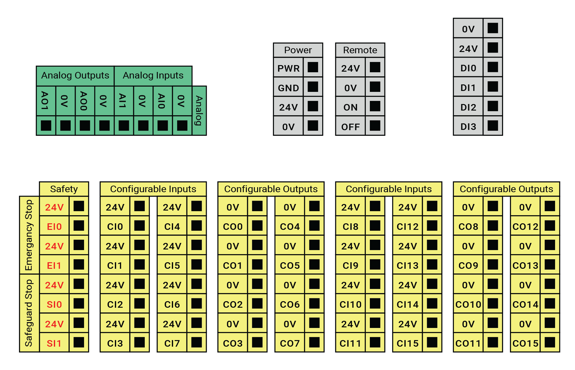
The illustration below shows the layout of electrical interface groups inside the Control Box. Observe and maintain the color scheme as illustrated below.

 
Yellow with red text Dedicated safety signals
Yellow with black text Configurable I/Os
Gray with black text External power, remote ON/OFF and digital input
Green with black text General purpose analog I/O
CB7 Controller I/Os


Configurable I/O are I/O configured as either safety-related I/O or general purpose I/O. These are the yellow terminals with black text.
Digital I/O specification

The digital I/Os are constructed in compliance with IEC 61131-2. The electrical specifications are shown below.

Terminals Parameter Min Typ Max Unit
Digital Outputs


[COx / DOx] Current* 0 - 1 A
[COx / DOx] Voltage drop 0 - 0.5 V
[COx / DOx] Leakage current 0 - 0.1 mA
[COx / DOx] Function - PNP - Type
[COx / DOx] IEC 61131-2 - 1A - Type
Digital Inputs


[EIx/SIx/CIx/DIx] Voltage -3 - 30 V
[EIx/SIx/CIx/DIx] OFF region -3 - 5 V
[EIx/SIx/CIx/DIx] ON region 11 - 30 V
[EIx/SIx/CIx/DIx] Current (11-30 V) 2 - 15 mA
[EIx/SIx/CIx/DIx] Function - PNP + - Type
[EIx/SIx/CIx/DIx] IEC 61131-2 - 3 - Type

*For resistive loads or inductive loads of a maximum of 1 H.