
What is a singularity?
This article explains the concept of a Singularity and where you may encounter them within the UR system
Created Date: July 17, 2018
Hint: The images on this document are .gif files, they will load after some seconds, wait for it to fully load it to understand the concepts.
When programming a robot to do a task, we generally think in terms of the way the robot tool moves in its workspace and describe this as movements relative to X, Y and Z axes in 3D or Cartesian space. The robot itself however needs this to be converted into a target angle for each of its six joints in order to be able to move the tool to the intended position. We call this conversion process kinematics, and with articulated robot arms like those in the UR product range, there are inevitably some difficulties with this conversion in certain situations.
There are three main scenarios where a UR robot may have problems moving to a position, either because it is physically not possible for the robot to reach the required position, or because it’s not possible to get there from the current position of the robot joints. Here we will broadly categorise these situations as singularities, and explain them one by one.
Robot workspace
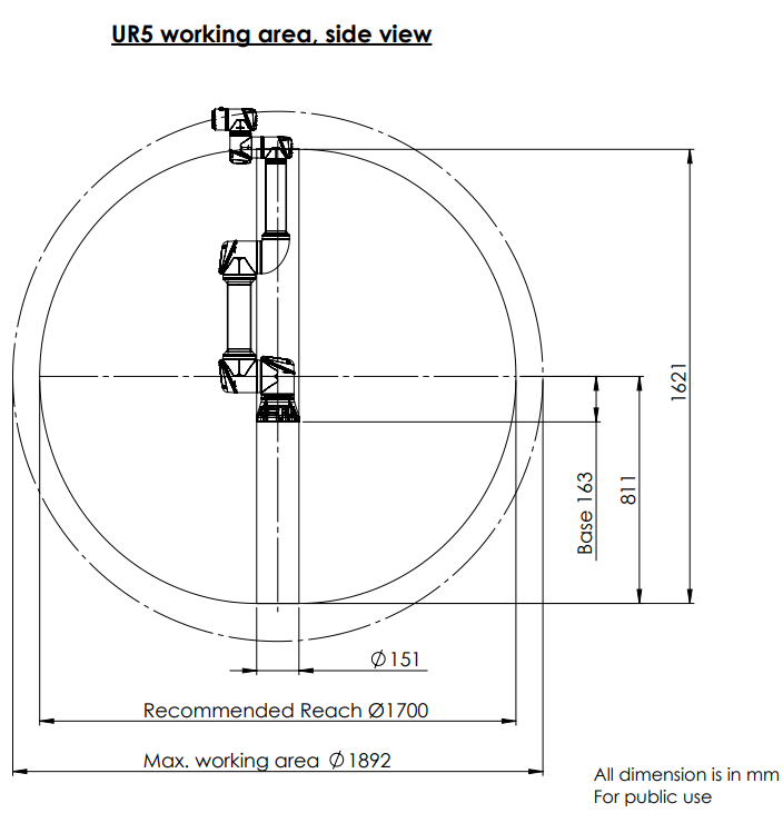
The workspace of a UR arm is spherical, and in the working area diagrams that you’ll find under the support site it’s represented with two concentric circles, a smaller one labelled “Recommended Reach” and a slightly larger one labelled “Max. working area”. In the centre of the workspace, directly above and below the base joint there is a column, inside which there are also some restrictions on robot movement. The example below is from the UR5e robot working area diagram that can be found here:
Robot working area - Drawing no. 1000698
Outer Workspace Limit
The animation below shows that within the recommended reach sphere (represented in blue), the robot can move the tool to any position with almost any orientation. When working in the area outside of the recommended reach, but still within the max working area (represented in grey), most positions can be reached but with restrictions on the tool orientation, because the robot physically cannot reach far enough in some situations.
How to avoid
Arrange the equipment around the robot to avoid working outside of the recommended workspace, or if this is not possible, select a UR robot with a longer reach.
Inner Workspace Limit
It is recommended to avoid robot movements in the column directly above and below the robot base (represented in grey in the animation below), as many positions/orientations will be physically unreachable due to the way the joints are laid out on the robot arm. Additionally, you may have issues performing linear movements in the space just outside of this cylinder (represented in orange), as a relatively slow tool speed requires a very high speed of rotation of the base joint, making some tool movements unachievable or unsafe.
How to avoid
Layout the robot task in such a way that it is not necessary to work in or close to the central cylinder. If this is unavoidable, use MoveJ with "Use joint angles" option instead of MoveL where possible, as this does not require kinematic conversion and is not affected by Singularities. You can also consider mounting the robot base on a horizontal surface to rotate the central cylinder from a vertical to horizontal orientation, potentially moving it away from the critical areas of the task.
Wrist Alignment Singularity
The shoulder, elbow and wrist 1 joints all rotate in the same plane on UR robots, as shown by the arrows numbered 1, 2 and 3 in the animation below. However when we also align the movement of wrist joint 2 (labelled 4 in the animation) with this same plane by moving it to an angle of 0 or 180 degrees, we limit the range of movements of the robot, regardless of the area of the workspace.
How to avoid
Layout the robot task in such a way that it is not necessary to align the robot wrist joints in this manner. Alternatively offset the direction of the tool, so that the tool can point horizontally without the problematic wrist alignment. Also, if the linear motion is not necessary, MoveJ with "Use joint angles" option would help to reduce the singularity issue.