
Setting Up Safety Boundaries
Example of How to Setup a Safety Boundary
Example is valid for:
CB3 Software version: 3.1.17779
Note that older or newer software versions may behave differently.
This example can be used for CB3/CB3.1.
A Safety Boundary is used to protect personnel or peripheral equipment by defining a wall and either preventing the robot from traveling through it or by causing the robot to enter Reduced Mode.
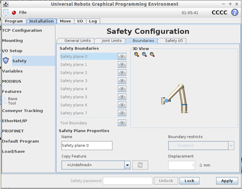
Figure 1 - Safety Boundary Screen
How to Setup a Safety Boundary
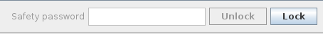
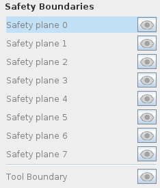
To setup a Safety Boundary go to Installation > Safety > Boundaries (seen in Figure 1). Enter your safety password to unlock and manipulate the safety settings (Figure 2). Now select which safety plane boundary you want to define, you have eight to choose from: Safety Planes 0-7 (Figure 3).
 |
 |
|
Figure 2 - Password Field
|
Figure 3 - Safety Boundaries
|
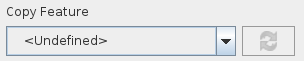
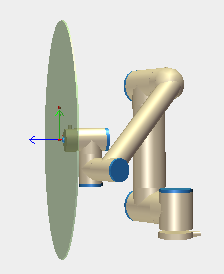
Once selected choose which feature to copy under the “Copy Feature” pull down (Figure 4). The feature that’s selected will determine the location and orientation of the safety plane. For instance, a feature that has a vertical position (Figure 5) due to its coordinate system will result in a Safety Plane of the same orientation.
 |
 |
|
Figure 4 - Copy Feature
|
Figure 5 - Vertical Feature/Boundary Position
|
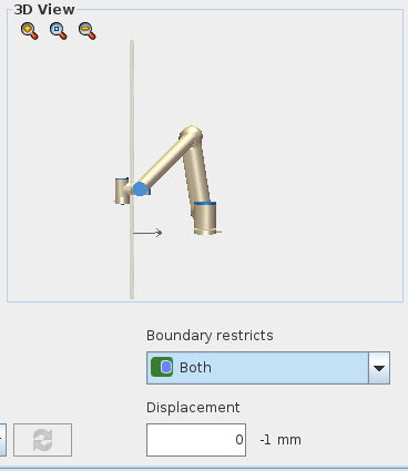
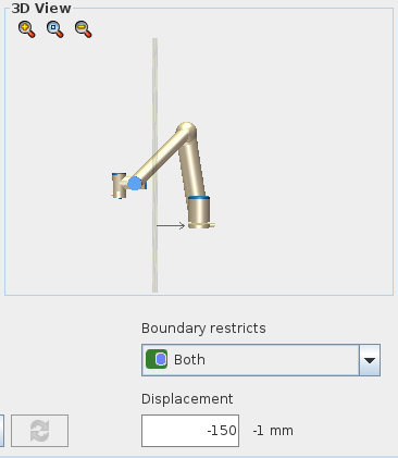
Once the feature is selected you can choose whether you want to displace it or not (Figure 6). This will not change the orientation of the coordinate system/feature but rather move the physical location closer or further from the robot, the graphic on the screen will show you the current location of the boundary and will move as you change the displacement input (Figure 7).
 |
 |
|
Figure 6 - Displacement of 0 with Graphic
|
Figure 7 - Displacement of -150 with Graphic
|
Finally, choose what restriction you’d like the wall to represent (can be seen in article: Understanding the Safety Boundary Restricts - 29986). After making sure everything is correct click the Apply button and then Confirm the new Safety Parameters.
A finished Safety Boundary screen can be seen below in Figure 8.
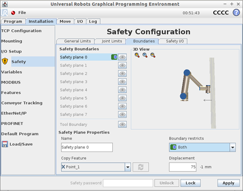
Figure 8 - Boundary Screen with Boundary Created