
PROFInet How-To Guide CB3
This guide gives a step-by-step instruction on how to start using PROFINET with CB3 Universal Robots.
NOTE: All files are available for download at the bottom of this page.
This guide is valid for:
CB3 Software version: 3.3
Note that older or newer software versions may behave differently.
1. setup
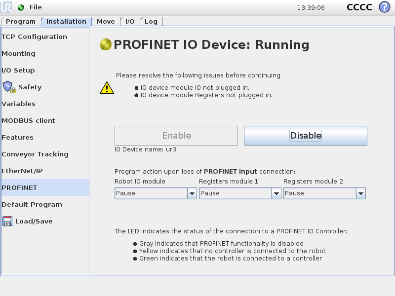
1. ROBOT: Enable PROFINET in the Installation tab. Remember to save the installation afterwards for the changes to take effect the next time the installation is loaded.
| CB3 |
 |
2. ROBOT:The yellow LED indicates that PROFINET is running on the robot but no PLC/IO controller is connected to the robot.
| CB3 |
 |
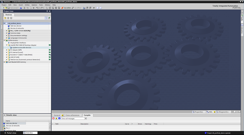
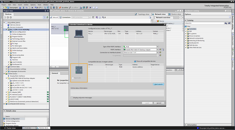
3. PLC: Open a project in Siemens TIA Portal. In the Project Tree of the Project view, navigate to: Online access -> {your network adapter} and click "Update accessible devices".
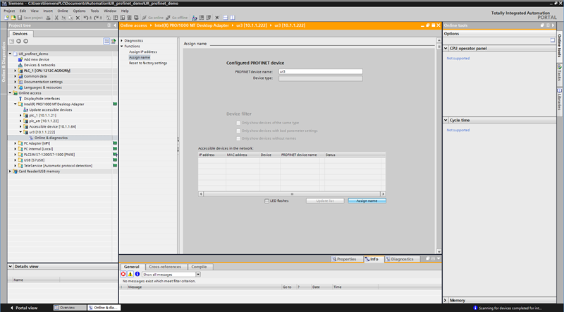
4. PLC: Identify the robot and the PLC that you want to connect and assign IP addresses and names to the equipment. Expand the desired accessible device and double-click "Online & diagnostics". In the device's diagnostics page, expand Functions and click "Assign IP address", enter the desired IP address and subnet mask, and press "Assign IP address". Still in the diagnostics page click "Assign name" and set the "PROFINET device name" and press "Assign name". Name should be in lower case only.
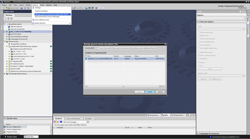
5. PLC: Import the Universal Robots' GSD file by clicking Options -> "Manage general station description files (GSD)" -> navigate to the right GSD and install.
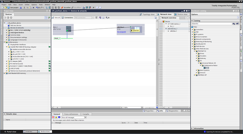
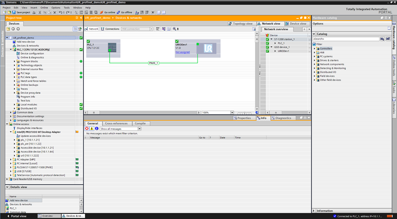
6. PLC: In the top of the project tree go to "Devices & networks" and locate the UR I/O device from the catalog path "Other field devices" -> "PROFINET IO" -> I/O -> Universal Robots A/S -> Collaborative Robot -> V1.0. Drag-and-drop it into the network view and connect the PLC and the I/O device by dragging a line between their (green) PN/IE ports.
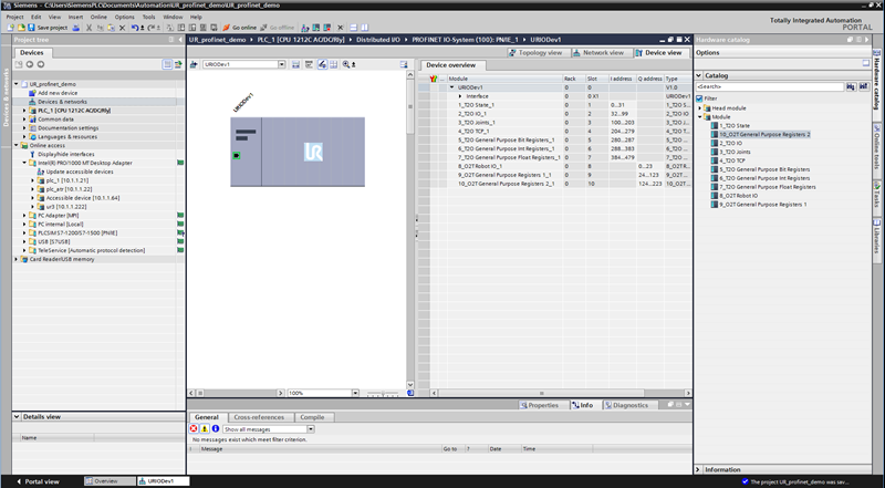
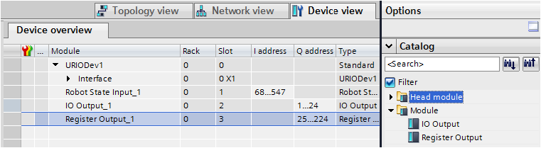
7. PLC: Double-click the I/O device in the Network view. All modules are pluggable, and are named according to their corresponding slot numbers. Each module can be drag-and-dropped from the Catalog -> Module to the empty fields in the Device overview. In this example all modules are plugged in. Notice how the input addresses (I) and output addresses (Q) are assigned, since you will need these to access the data.
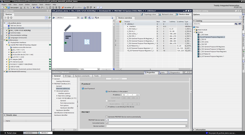
8. PLC: Double-click the I/O device in the Device view to get the module description. In the General tab select "Ethernet addresses" and check "Use IP protocol" and set the same IP address as was assigned to the online device, uncheck "Generate PROFINET device name automatically" and type in the same "PROFINET device name" as was assigned to the online device.
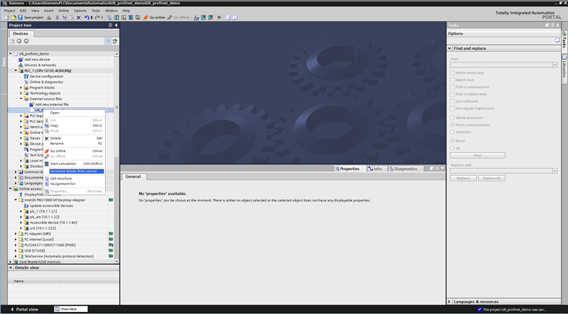
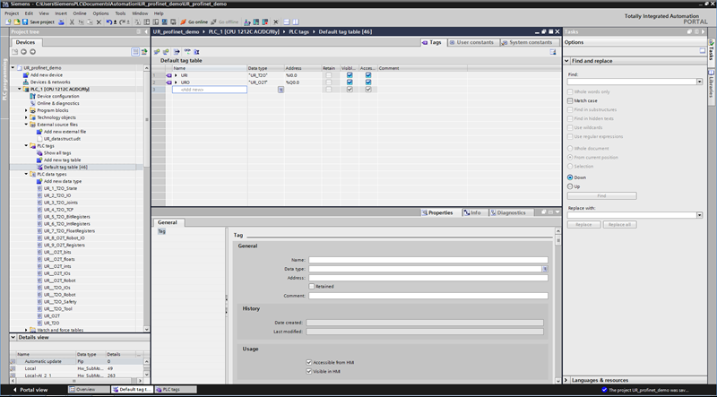
9. PLC: This step requires PLC firmware version 4.0 or higher. Navigate to "External source files" and double-click on "Add new external file" in the project tree and open the file UR_datastruct.udt. Import the user-defined data types by right clicking the newly added external source file and select "Generate blocks from source". In the "PLC tags" (or your own Data Block) create tags that correspond to the modules you have enabled. Make sure that the input addresses (I) and output addresses (Q) of the tags match those of the modules. If all modules are enabled and placed in order in the IO memory you only need to create a single PLC input tag of the data type "UR_T2O" and a single PLC output tag of the data type "UR_O2T" to map all data. They are both visible in "PLC data types" in the project tree.
10. PLC: Download the program to the PLC: click the Download icon in the menu bar, "Start search" in the download dialog, select the plc and click "Load"
11. PLC: Confirm that all blocks, tags and modules in the project tree are green
12. ROBOT: Confirm that the LED in the Installation tab is also green
| CB3 |
 |
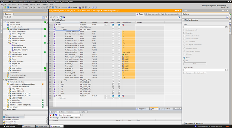
13. PLC:In the project tree, navigate to your tag table (or Data Block) and expand your input tag to inspect values sent from the robot
2. Specifications
Here is an overview of some important information to get started.
2.0.1. Demo Sample Program
Sample files for this example are available for download at the bottom of this page:
- UR_profinet_demo.zap13: archived project file that can be loaded into the TIA Portal v13 (choose "Project"->"Retrieve")
- ur-pn-demo.urp: demo program for the robot
PLC (used in example)
- Siemens S7-1200, 1212C AC/DC/Rly
- Totally Integrated Automation Portal V13, STEP 7 Basic
Robot
- UR3, UR5 or UR 10 running PolyScope v. 3.3
2.0.2. I/O Message Format
Overview of the IO format and how it is distributed between the modules is found in the file pn-iomessage.pdf
The Robot has 10 pluggable modules: 7 modules contain the data that can be read from the robot, and additional 3 contain data that can be set on the robot. All modules are optional, but are fixed to a specific slot according to their names: e.g. the UR_3_T2O_Joints can be plugged into slot 3, contain data from the robot (T) to the PLC (O), namely joint measurements.
Note: When using output I/Os, it is important to set the mask accordingly.
User-defined Data Types
- For PLCs S7-1200 and S7-1500 (PLC Firmware v4.0 or higher): UR_datastruct.udt (can be imported into TIA Portal)
- For PLCs S7-200, S7-300 and S7-400: URI.AWL, URO.AWL (can be imported into SIMATIC and TIA Portal)
The UDT/AWL files contain user-defined data types and can be used to import the message format.
Note: If you import the UR data structure (the .udt file) and only plug in some of the modules, make sure to use the right user defined data types and match the input address (I) or output address (Q) of the module with the address of the data types in the tag table. This is also necessary if you drag the modules in "out of order", e.g. the module to slot 5 before the module to slot 2.
GSD file
GSDML-V2.31-ur-UR-20160505.xml (thumbnail image: GSDML-0361-0001-UR.bmp)
2.0.3. Script Functions
Script Functions for synchronizing a program with a PLC:
- read_input_boolean_register(address)
- read_input_float_register(address)
- read_input_integer_register(address)
- read_output_boolean_register(address)
- read_output_float_register(address)
- read_output_integer_register(address)
- write_output_boolean_register(address, value)
- write_output_float_register(address, value)
- write_output_integer_register(address, value)
2.0.4. Notes
- If you change the IP of the robot in Network Settings while PROFINET is enabled, you need to disable PROFINET and enable it again before the changes take effect. If the IP of the robot is changed using external PROFINET tools, e.g. through the TIA software, the changes will take effect immediately.
- The lower range (bool[0:63], int[0:23], float[0:23]) of the gp input and output registers is reserved for FieldBus/PLC interface usage. The upper range (bool[64:127], int[24:47], float[24:47]) can be used by external RTDE clients (i.e URCAPS).
3. Demo
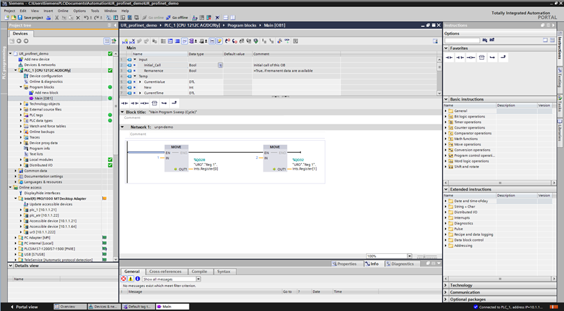
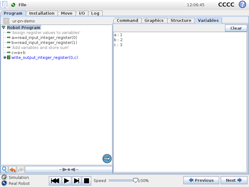
This demo is provided to show a basic example of how to communicate between the PLC and Robot. The demo allows the user to set two numbers in PLC output registers. The robot retrieves the numbers, calculates their sum and stores the result in a PLC input register.
1. PLC: Navigate to the Main Program Block and set integer registers URO."Reg 1".Ints.Register[0] and URO."Reg 1".Ints.Register[1] to some values and download the program to the PLC
2. ROBOT: Open ur-pn-demo.urp and run the program. Navigate to variables tab and confirm that the numbers are received
| CB3 |
 |
4. Robot Modes
| Mode | Description |
| -1 | ROBOT_MODE_NO_CONTROLLER |
| 0 | ROBOT_MODE_DISCONNECTED |
| 1 | ROBOT_MODE_CONFIRM_SAFETY |
| 2 | ROBOT_MODE_BOOTING |
| 3 | ROBOT_MODE_POWER_OFF |
| 4 | ROBOT_MODE_POWER_ON |
| 5 | ROBOT_MODE_IDLE |
| 6 | ROBOT_MODE_BACKDRIVE |
| 7 | ROBOT_MODE_RUNNING |
| 8 | ROBOT_MODE_UPDATING_FIRMWARE |
5. Video Guides
Italian Original : Profinet connection between robot and PLC - YouTube
English Translated : Profinet connection between robot and PLC - YouTube
6. Example Image of Failsafe Library
