
Communication between Teledye Dalsa Vision system and Universal Robots
Example is valid for:
CB3 Software version: All versions
e-Series Software version: All versions
Note that older or newer software versions may behave differently.
Introduction
The purpose of this document is to provide a guide on how to communicate between a Teledyne Dalsa camera and a Universal-Robots arm. This guide will utilize an application where cogs placed on a conveyor are identified by the vision system. The position data and size of the cogs are then transferred to the Universal-Robots arm for manipulation. The mode of communication between the Vision system and The Universal-Robots arm will be socket commands.
Process Flow
The figure below is a representation of the process flow of the application. The communication method and script examples are also displayed in the red boxes.
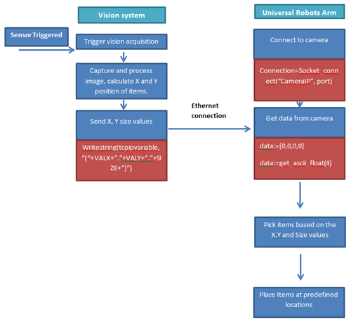
[Table 1: Process flow of application]
Camera set up
To change the settings for the camera, users can assess it by connecting to the camera using a browser. After connection, the options below are available to the user.
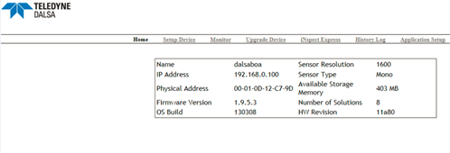
[Figure 1: Teledyne Dalsa Set-up page]
Solutions
Application specific solutions can be created via the tools tab. As seen in the figure below. Once a satisfactory solution has been obtained, transfer the data over to the robot. The X,Y and Size values will be written to the variables VALXVALY and SIZE respectively.
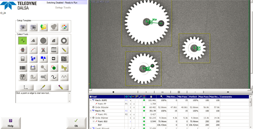
[Figure 2:Solution editor]
Setup Control/Communications
The Vision system and the robot will communicate via socket commands, to achieve this; the user has to configure the connection type in the control tab.
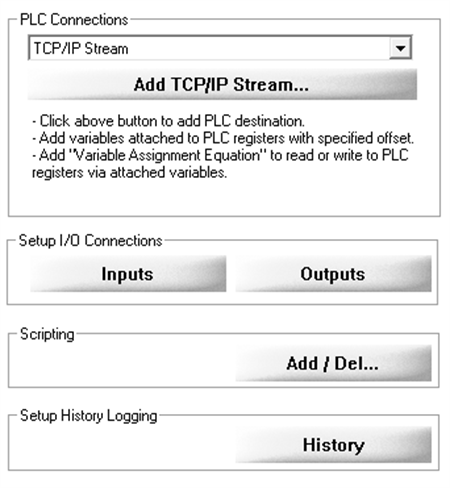
[Figure 3: Communication settings on vision system]
In this example the camera will act as a server, data will be requested by the robot. Set the port value accordingly, in this case 5024. Set the variable name of the communication method. This can be seen in the figure below.
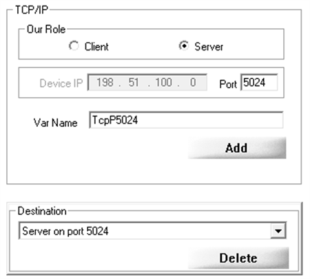
[Figure 4: Server settings and TCP/IP Variable]
Configure the data type to send over by selecting the communications protocol TCP/IP stream and perform custom scripting. Access the functions by clicking on the item below.
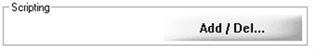
[Figure 5: Scripting functions]
Select free edit function to customise solutions. In this example we send data by using the Writestring(tcpipvariable, “(“+VALX+”.”+VALY+”.”+SIZE+”)”), the values contained in variables VALX, VALY and SIZE will be sent to the robot.
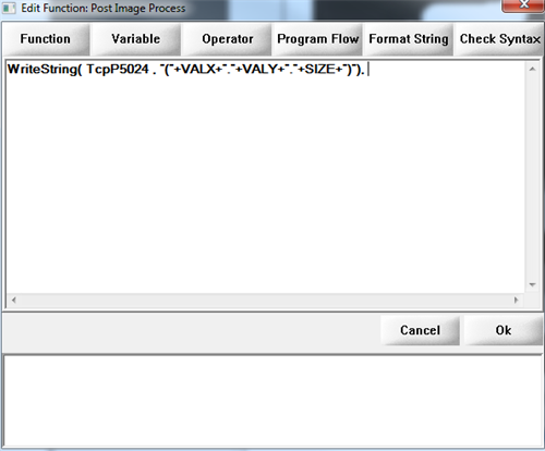
[Figure 6: Custom scripting code]
Robot Program
From the Universal Robots arm, a connection to the Vision system has to be established. The user has to utilize the socket_open() function. The figure below shows a simple connection routine.
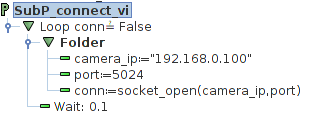
[Figure 7: Camera_ip, Port and conn are all variables.]
Getting data
To access data form the Vision system, the user will have utilize the function, socket_read_ascii_float(). The user also has to create a variable that has the appropriate size. The vision system sends data in a list, the first element on the list being the size of the data. As we are requesting three data points, VALY, VALX and SIZE, the Vision system will send data in this format. [3,VALY,VALX,SIZE]. The figure below shows the use of the function socket_read_ascii_float().
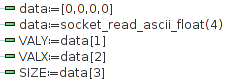
[Figure 8: Assignment of variables]
Aligning TCP with Vision frame
A quick method of aligning the vision frame from a camera with the robot is to create a user defined feature. Features planes can be created by going into the installation tab and selecting the features option. The illustration below shows that the centre point of the user defiled plane is aligned to the reference frame of the vision system.
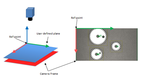
[Figure 9: Aligning camrea frame with user defined feature]
As the reference point of the user defined feature is directly mapped to the camera frame, offsetting the TCP relative to the feature frame with the use of the pose_trans() function would be relatively simple. The example below shows that the pick position is a pose transformation of the camera frame and an offset based on the coordinates of the objects.
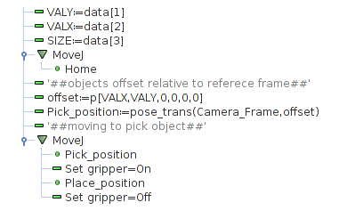
[Figure 10: Using pose_trans() to offset pick position]