Planes
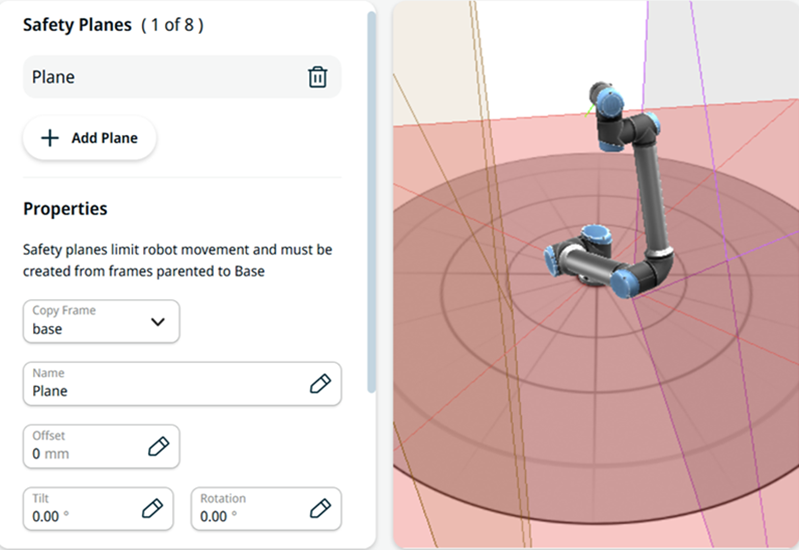
| Configuring a Safety Plane |
You can configure safety planes with the properties listed below:
You can configure each plane with the restrictions listed below:
|
| Elbow Joint Restriction |
The feature is enabled by default. You can use Restrict Elbow to prevent the robot elbow joint from passing through any of your defined planes. Disable Restrict Elbow to allow the elbow to pass through planes.
|
| Tool flange Restriction |
Restricting the tool flange prevents the tool flange and the attached tool from crossing a safety plane. When you restrict the tool flange, the unrestricted area is the area inside the safety plane, where the tool flange can operate normally. The tool flange cannot cross the restricted area, outside the safety plane. Removing the restriction allows the tool flange to go beyond the safety plane, to the restricted area, while the attached tool remains inside the safety plane. You can remove the tool flange restriction when working with a large tool offset. This allows extra distance for the tool to move. Restricting the tool flange requires the creation of a plane feature. The plane feature is used to set up a safety plane later in the safety settings. Safety planes are defined in relation to a frame defined in the installation or the robot world frame. The robot is allowed to move such that all monitored parts of the robot arm and user-defined safety spheres are in front of the plane.
|
|
Wrist joint Restriction |
When a safety plane restricts the tool flange position, it also restricts the position of the wrist joints. This prevents the wrist joints from penetrating the plane, so both the tool flange and the wrist joints remain inside the unrestricted area of the safety plane. For a reduced mode plane, the position of the wrist joints also triggers Reduced mode, in the same way as the tool flange. When a wrist joint moves beyond a reduced mode plane, the safety system switches to Reduced mode. Wrist joint monitoring is coupled to tool flange monitoring. When you disable monitoring of the tool flange, you also disable monitoring of the wrist joints. Wrist joint restriction follows the tool flange restriction setting for each safety plane. When you remove the tool flange restriction to allow extra distance for a large tool offset, the wrist joints are no longer restricted by that plane. Verify that other means mitigate any resulting risk of the wrist joints crossing the plane.
|