Force Mode

Description

The Force Mode command enables you to set force and speed limits in the X, Y, Z, RX, RY, and RZ directions. Use it when you need to control contact force or a torque about an axis, rather than hold an exact pose on that axis. Apply it when you push, pull, roll along a surface, or follow a path while applying a side force. If nothing contacts a compliant axis with a non-zero wrench, the arm accelerates along that axis to the configured speed limit.


To access the Force Mode command

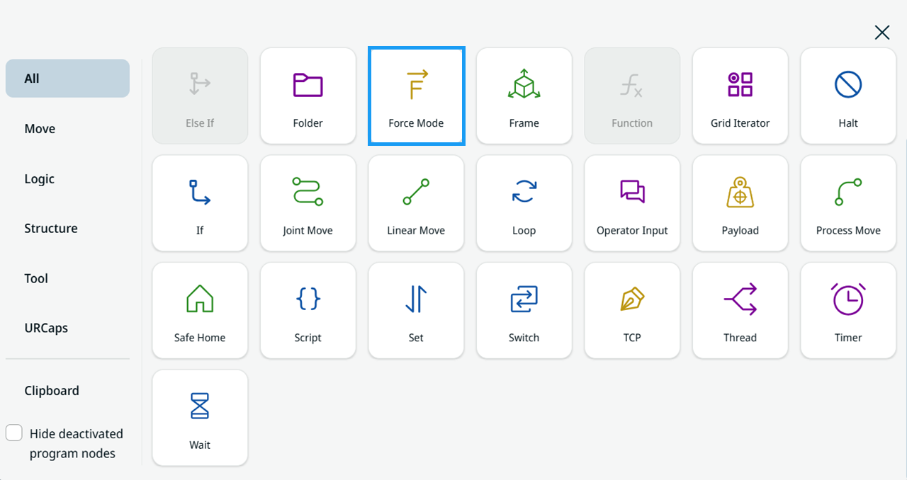
  1. Tap the Force Mode icon in the Commands toolbox.

    Force Mode icon in the Commands toolbox
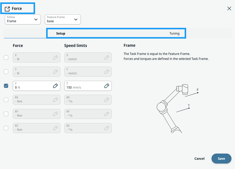
  2. The Force Mode button is inserted into the program tree. Tap the Force Mode button. The Force screen opens with tabs and the Setup and Tuning panels.

    Force screen with the Setup and Tuning panels


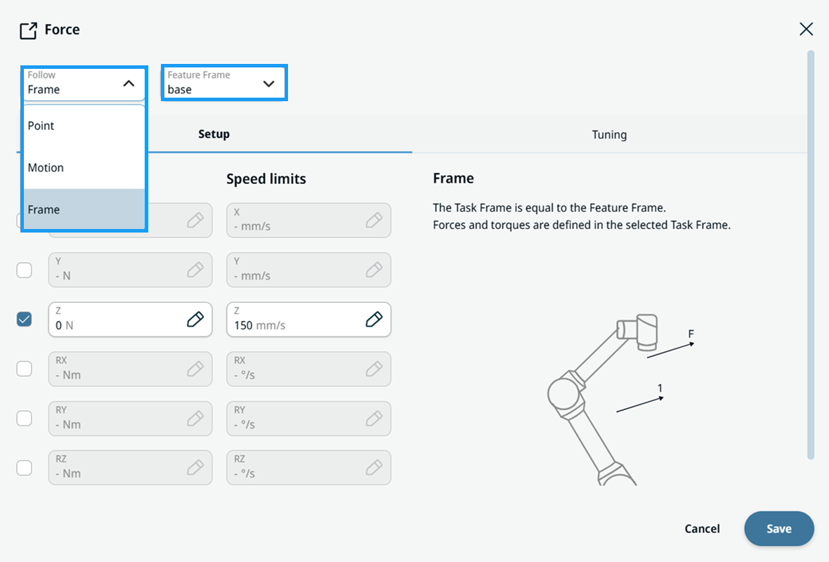
Follow and Feature Frame fields

Follow field open with the Point, Motion, and Frame options, next to the Feature Frame field

In the Follow field, select one of three modes: Point, Motion, or Frame.

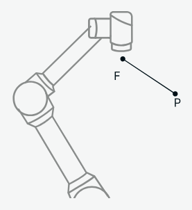
  1. Point

    • The Feature Frame is a point.

    • The task frame Y+ axis points toward the selected point.

    • Use this mode to apply force toward the center of a circular path.

      Point mode: force F directed toward the selected point P
    Do not specify forces in the X or Z direction.


  1. Motion

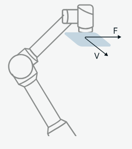
    The task frame follows the TCP movement direction:

    • The X axis aligns with the motion projected in the X-Y plane of the Feature Frame.

    • The Z axis is parallel to the Z axis of the Feature Frame.

      Motion mode: force F and movement direction V in the X-Y plane of the Feature Frame
    This mode is active only while the robot is moving. The orientation remains that of the most recent motion.
  2. Frame

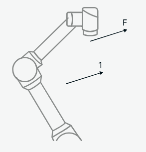
    • The task frame matches the Feature Frame.

    • Forces and torques are defined in the selected task frame.

      Frame mode: force F defined along an axis of the selected task frame

In the Feature Frame field, select:

  • Base

  • TCP

  • World

  • Flange

  • Frame


Setup panel

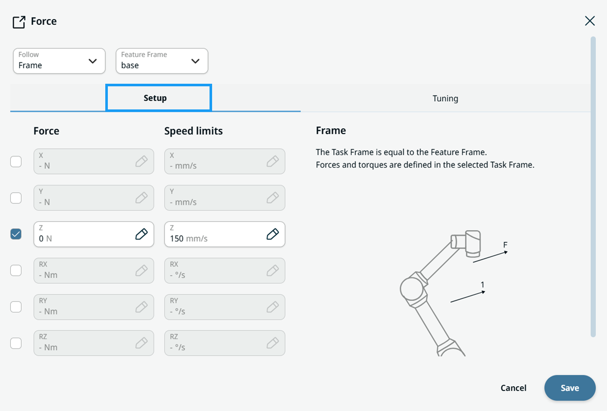
Setup panel with the Force and Speed limits fields for X, Y, Z, RX, RY, and RZ
  1. Tap the check boxes for X, Y, Z, RX, RY, and RZ to activate them.

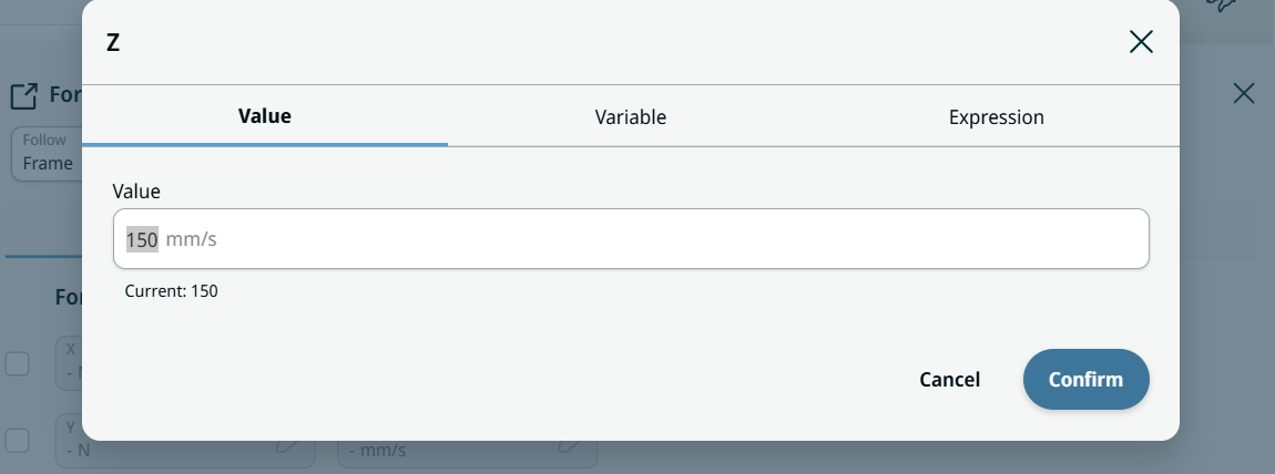
  2. In the Force and Speed Limits fields, use the Value, Variable, and Expression tabs and the Expression Editor.

    Value, Variable, and Expression tabs for the Z speed limit
  3. After you set the force and speed limits, tap Save.


Tuning panel

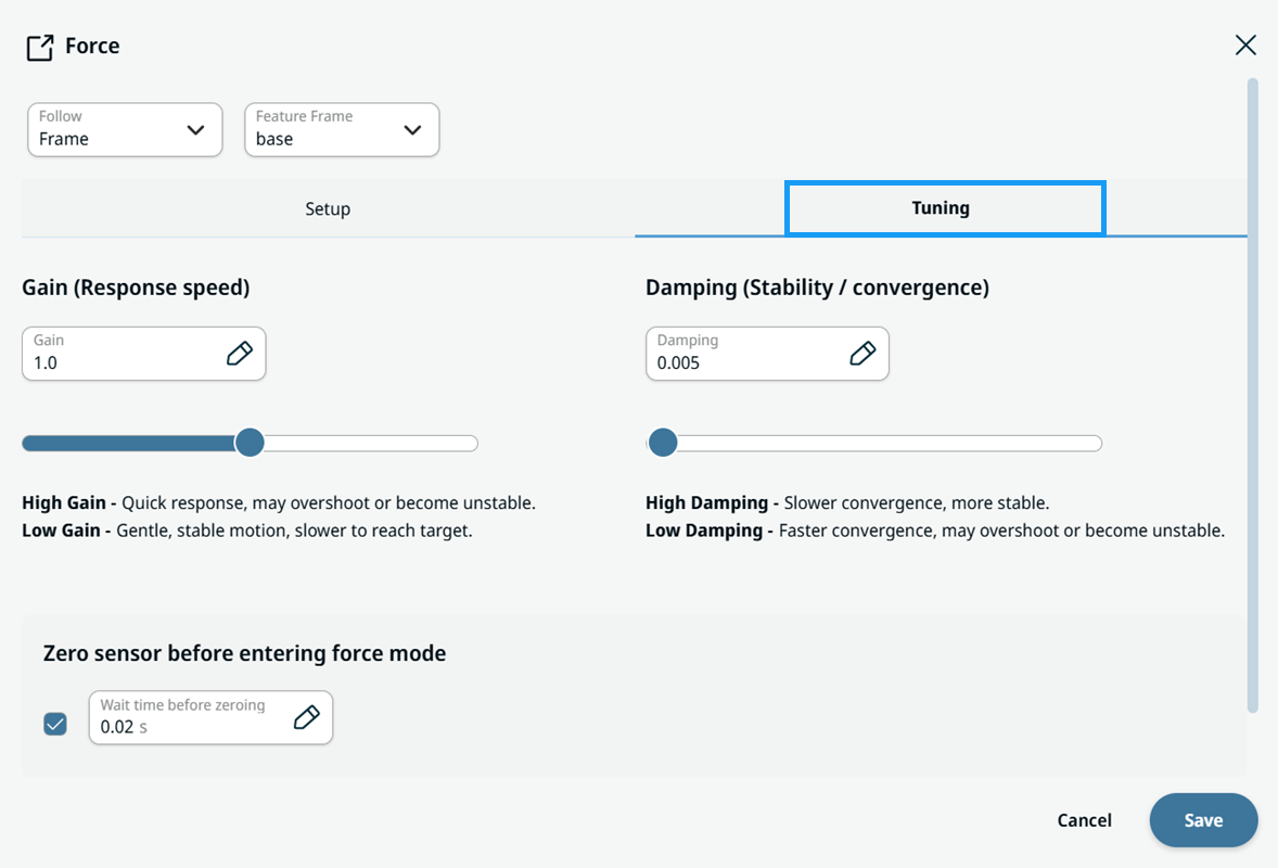
Tuning panel with the Gain, Damping, and Zero sensor settings

Tap Tuning, then use the Gain, Damping, and Zero sensor functions.

  • Gain defines how quickly the robot moves to reach the desired wrench.

  • Damping controls how quickly the robot discards the difference between the measured and desired wrench.

  • Zero sensor zeros the sensor when you enter force mode.

  1. Use the Gain slider or tab to set the gain level.

  2. Use the Damping slider or tab to set the damping level.

  3. Tap the Zero sensor check box to enable it and set the wait time.