SP7 Smart Panel
| Description |
The SP7 Smart Panel is an optional accessory for g-Series robots. It mates with the 12-pin spring-pin (smart panel) interface on the tool flange. The panel is detachable. You can remove it when the application does not need end-of-arm buttons or LEDs, or when a UR+ end-of-arm device uses the same interface. When mounted correctly, the robot arm and panel assembly are designed to maintain the environmental specifications of the robot arm, including ingress protection.
Typical uses include:
|
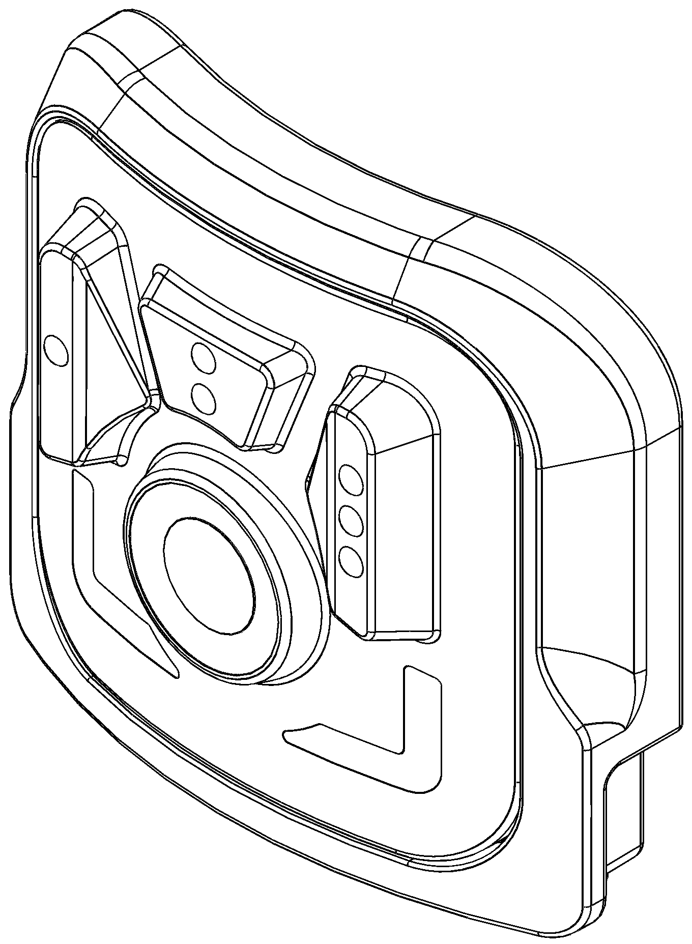
| System connection |
The smart panel connects only through the smart panel interface on the tool flange. For mechanical interface and pin electrical specifications, see documentation for the smart panel connector.
|
| Controls on the panel |
The smart panel has four buttons and two LED indicators on the housing. Do not confuse the large center control with the three smaller programmable buttons.
Integrator signal names (PTF Smart Panel connector, prefix T1_):
|
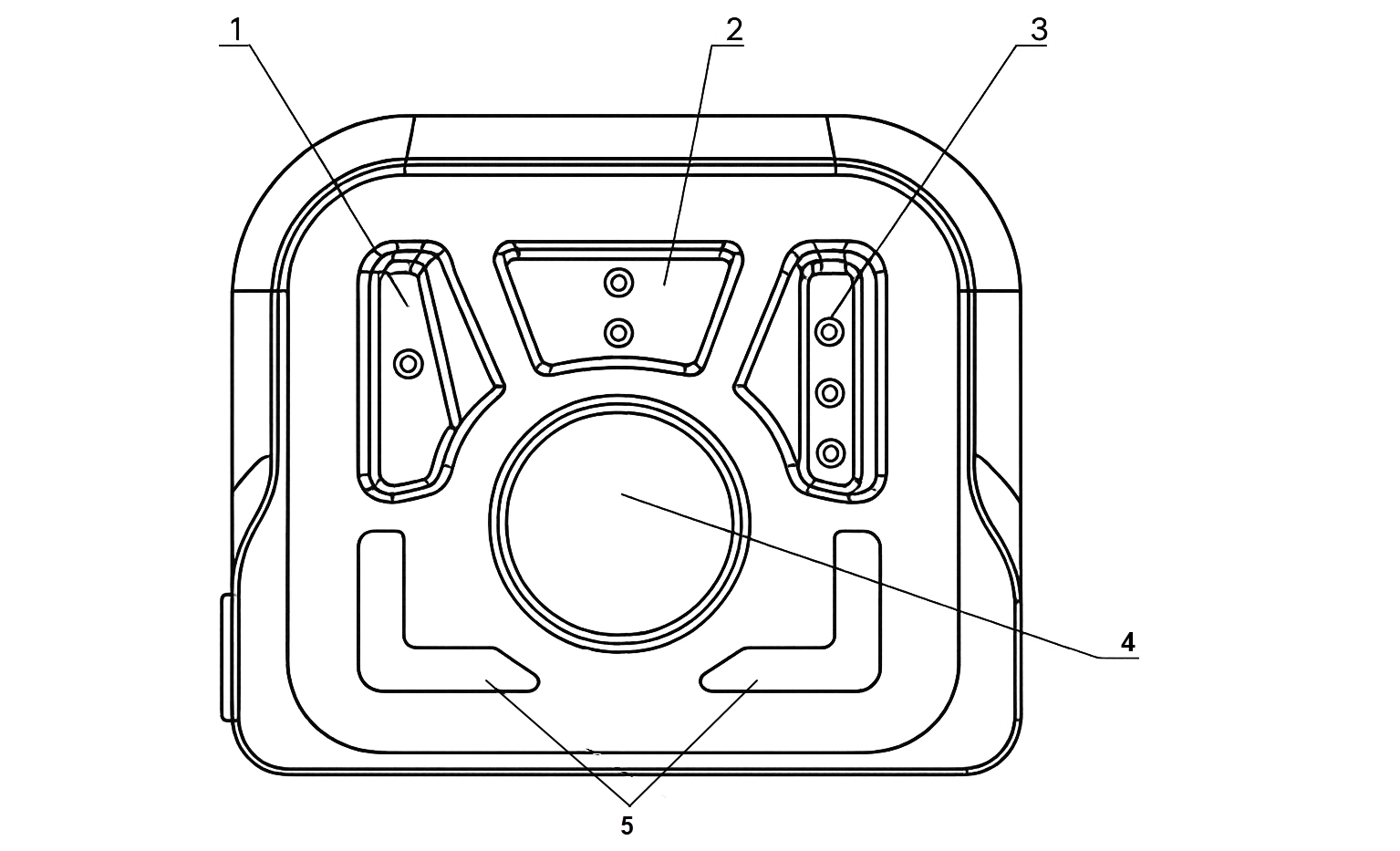
| Safety and Freedrive |
The center Freedrive button uses a safety-rated input on the smart panel interface (designed according to ISO 13849-1 Category 3 PLd; see Smart Panel Interface table). The safety system monitors this input; it is not assigned under Smart Panel or as a normal tool digital input action. You cannot enable or disable Freedrive on the panel from application software. Use the center button according to your risk assessment for hand-guided control and Freedrive at the end of the arm. Injury to personnel can occur due to unexpected motion in Freedrive.
Freedrive on robot in Safety I/O assigns other tool or control box inputs. It does not replace or configure the smart panel center Freedrive button. |
| Use Freedrive with Smart Panel |
|
| Configuring the Smart Panel in PolyScope X |
Configure what the three programmable buttons do in the Smart Panel source. Configure pin-level tool signals (including lamp outputs and input presets) in Tool I/O.
When a mapped button is pressed, PolyScope X toggles the assigned Smart Skill (starts it if inactive, stops it if already running).
Contributed Smart Skills from URCaps can be assigned the same way as native skills. Tool I/O (signals and lamps)
If a tool input is assigned a safety function, you cannot assign the same input an application action on the Tool I/O page. See Safety I/O for tool input rules. |
| Using buttons and LEDs in programs |
The three programmable buttons are available as digital inputs in URScript (when the hardware is present), for example: left_pressed = io_get("T1_DI0") io_set("T1_DO0", True) Lamp outputs use T1_DO0 through T1_DO3. Use the symbolic names shown in Tool I/O where the UI lists them. Programs and applications created for an older control box or tool flange without a smart panel may show invalid I/O or Smart Panel settings if loaded on a system with Smart Panel. Resolve yellow-marked settings before running production programs. |