M8 I/O 8-Pin
| Description |
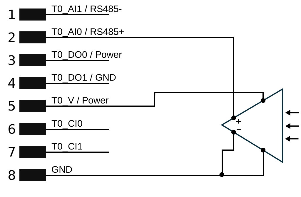
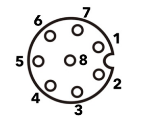
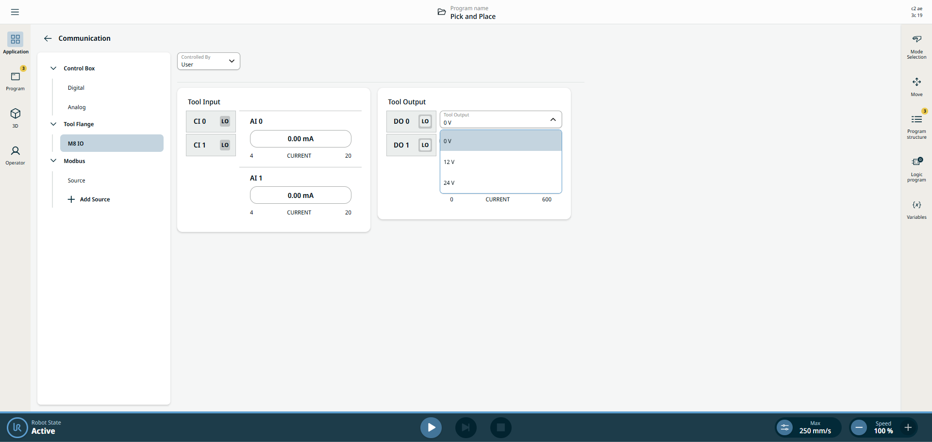
The 8-pin I/O M8 Tool Connector provides power and control signals for grippers and sensors used on robot tools. The tool connector has eight holes and is located next to the tool flange on Wrist 3. The eight wires inside the connector have different functions, as listed in the following table. All 8-pin I/O M8 Tool Connector signals are prefixed with "T0_". The electrical specifications are shown below. Access Tool I/O in the Installation Tab to set the internal power supply to 0 V, 12 V or 24 V.
* When connecting inductive loads, a protective diode shall be used.
|
Tool Power Supply
| Description |
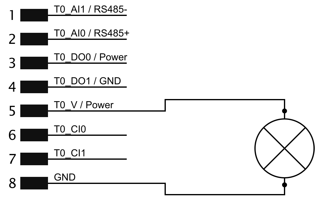
The tool power is supplied through dedicated power and ground pins in the tool connector. The output can be used to power external equipment directly from the robot without requiring a separate power source, provided the connected device remains within the specified electrical limits.
|
| Dual Pin Power Supply |
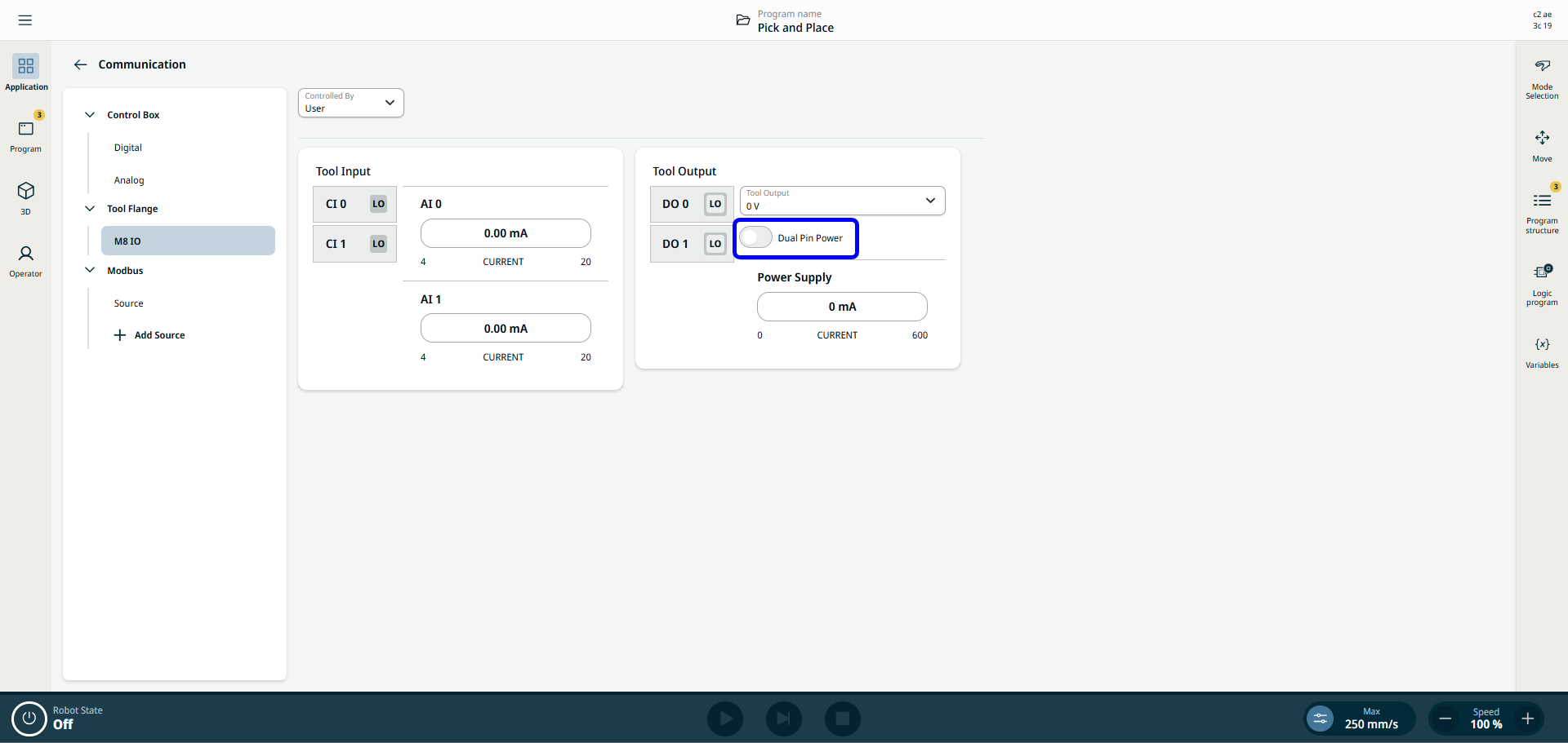
In Dual Pin Power mode, the output current can be increased as listed in Tool I/O.
After an Emergency Stop, the voltage is set to 0 V for both power pins (power is off).
|
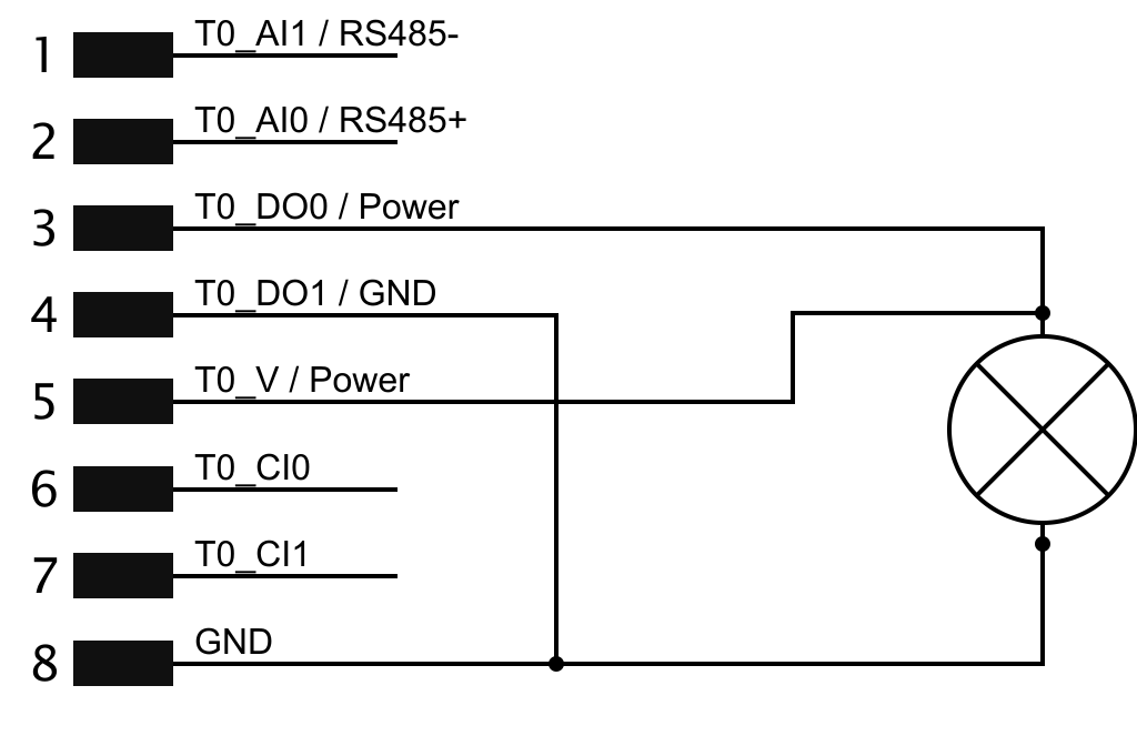
| Current through GND |
The electrical specifications are shown below:
* Peak for max 1 second, duty cycle max: 10%. Average current over 10 seconds must not exceed continuous current.
|
Tool Digital Inputs
| Description |
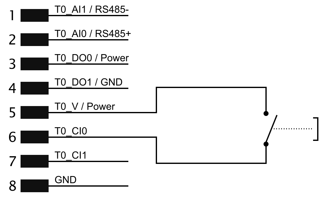
The Tool Digital Inputs allow external devices connected to the tool connector to provide signals directly to the robot controller. Typical applications include sensors, push buttons, part detection devices, and status signals from end-effectors. The state of the digital inputs can be monitored and used within robot programs to control robot behavior and application logic. |
|
The Digital Inputs are implemented as PNP with weak pull-down resistors. This means that a floating input always reads as LOW. The electrical specifications are shown below.
|
|
Using the Tool Digital Inputs |
Tool Digital Inputs enable external devices and sensors to send signals to the robot system. Configure Tool Digital Inputs to detect and respond to input signals from equipment connected to the tool.
|
||
|
Configuring Tool Digital Inputs |
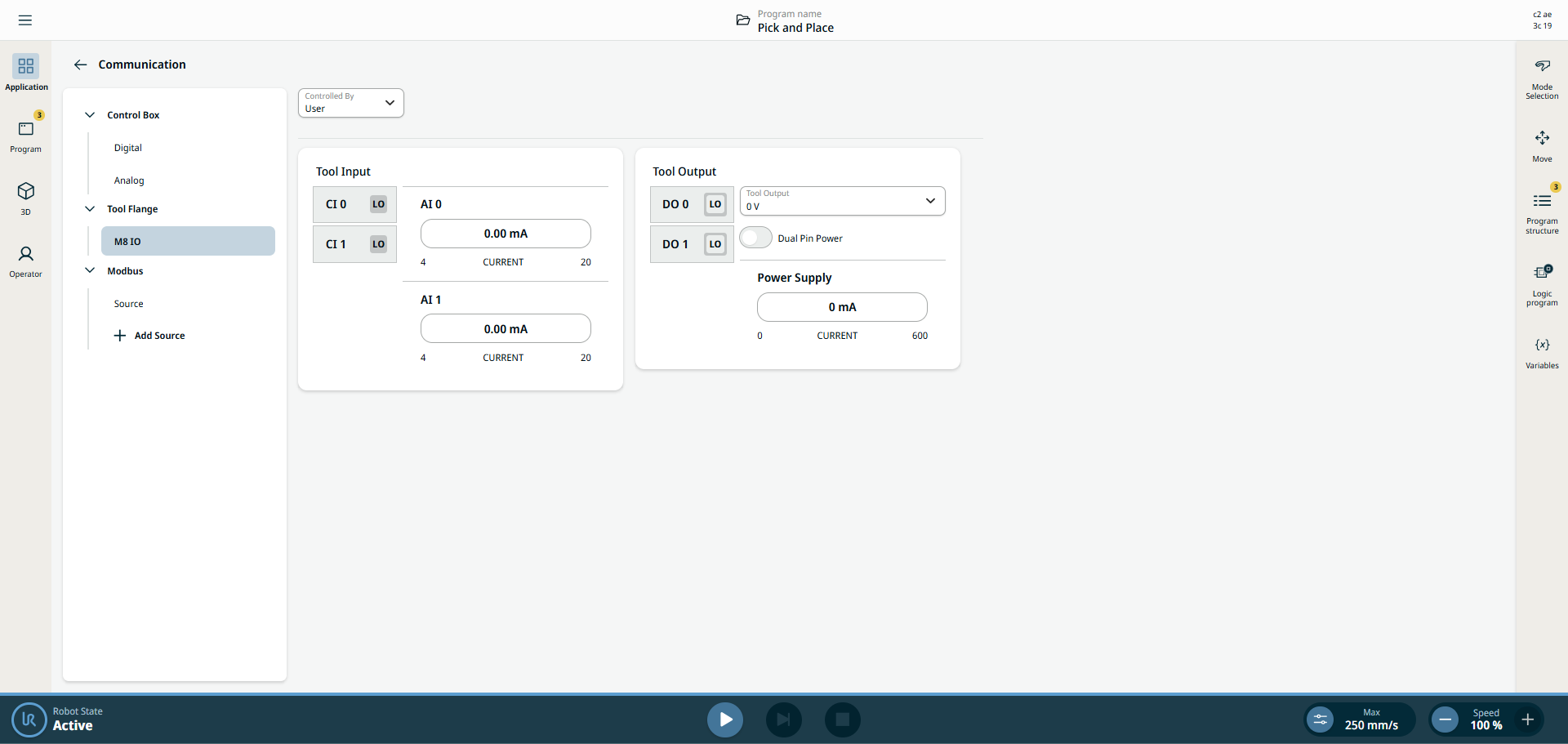
To configure Tool Digital Inputs in PolyScope X:
|
Tool Digital Outputs
| Description |
The Tool Digital Outputs allow the robot to control external devices connected to the tool connector, such as grippers, valves, indicators, relays, and other end-effectors. Output signals can be controlled from PolyScope X, robot programs, or URScript to interact with external equipment during robot operation. |
|
|
The Digital Outputs in the tool are not current-limited. Overriding the specified data can cause permanent damage.
|
| Output Modes |
The tool digital outputs are integrated into the tool connector and can be configured to operate in different output modes to support a wide range of external devices and control architectures.
Access Tool I/O in the Installation Tab to configure the output mode of each pin. The electrical specifications are shown below:
* Peak for max 1 second, duty cycle max: 10%. Average current over 10 seconds must not exceed continuous current.
|
| Using Tool Digital Outputs |
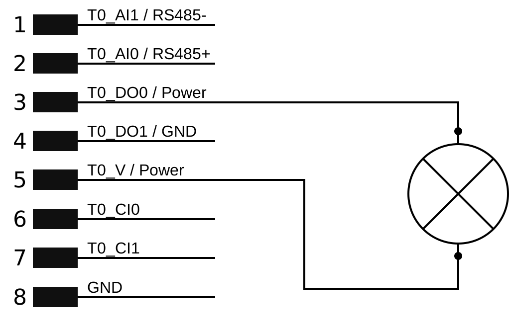
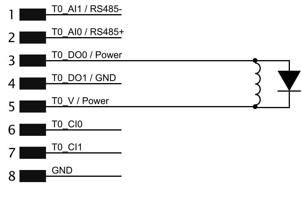
This example illustrates turning on a load using the internal 12 V or 24 V power supply. The output voltage at the I/O tab must be defined. There is voltage between the POWER connection and the shield/ground, even when the load is turned off.
When connecting inductive loads, a protective diode shall be used, as shown below.
|
Tool Analog Inputs
| Description |
Tool Analog Inputs are non-differential and can be set to either voltage (0-10 V) or current (4-20 mA) on the Communication>Tool Flange tab.
The electrical specifications are shown below.
Two examples of using Analog Inputs are shown in the following subsections.
|
|
Analog Inputs are not protected against overvoltage in current mode. Exceeding the limit in the electrical specification can cause permanent damage to the input. |
|
Using Tool Analog Inputs, Non-differential |
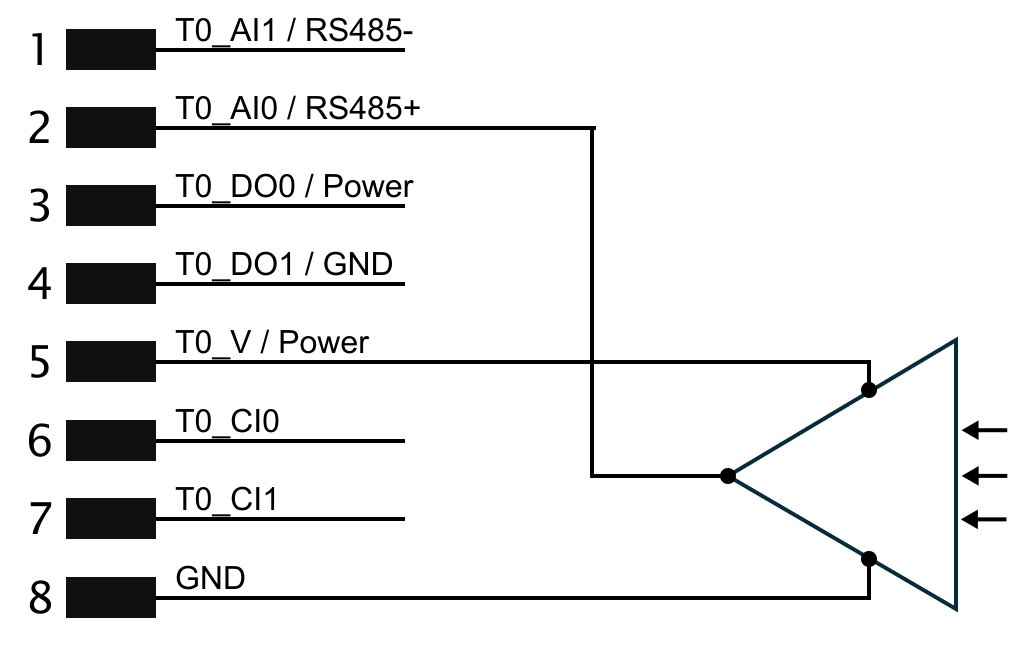
This example shows an analog sensor connection with a non-differential output. The sensor output can be either current or voltage, as long as the input mode of that Analog Input is set to the same mode in PolyScope X.
|
|
Using Tool Analog Inputs, differential |
This example shows an analog sensor connection with a differential output. Connecting the negative output part to GND (0 V) works in the same way as a non-differential sensor.
|