Setup
| Description |
Step-by-step configuration of the robot arm and Allen-Bradley PLC for Ethernet/IP.
|
|
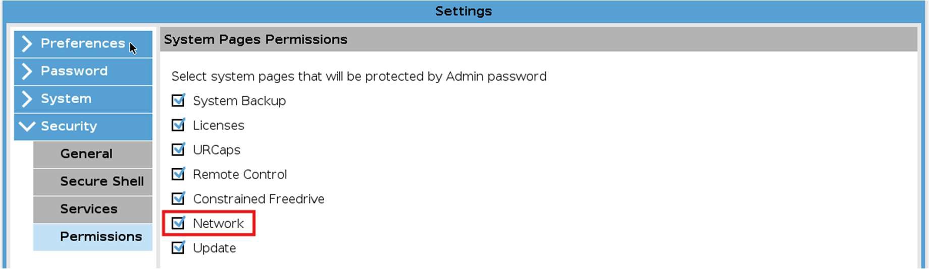
Robot Step 1: Enable EtherNet/IP in Services |
Enable EtherNet/IP in the Services Settings page.
Remember to save the installation afterwards so that the changes take effect the next time the installation is loaded.
|
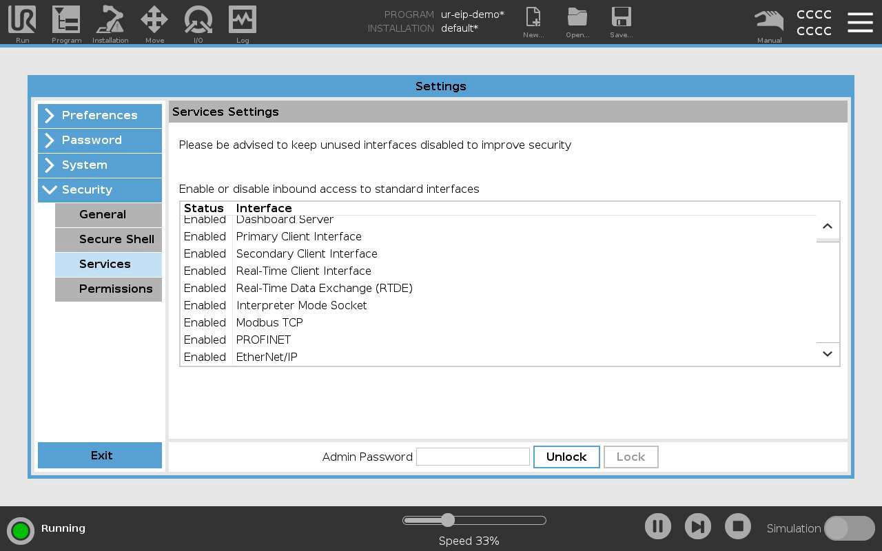
| Access to Service Settings |
Access to Service Settings may be protected by an admin password.
Remember to save the installation.
|
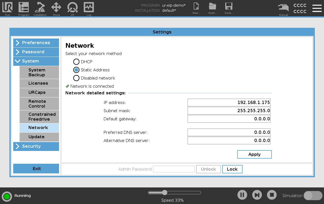
| Robot Step 2: Network settings |
Setup the robot IP address and network settings.
This requires the admin password.
Ensure that the robot has a unique IP on the same network as the PLC. The subnet mask must match the other devices on the network. The default gateway, preferred, and alternative DNS servers can all remain 0.0.0.0 for this demo.
|
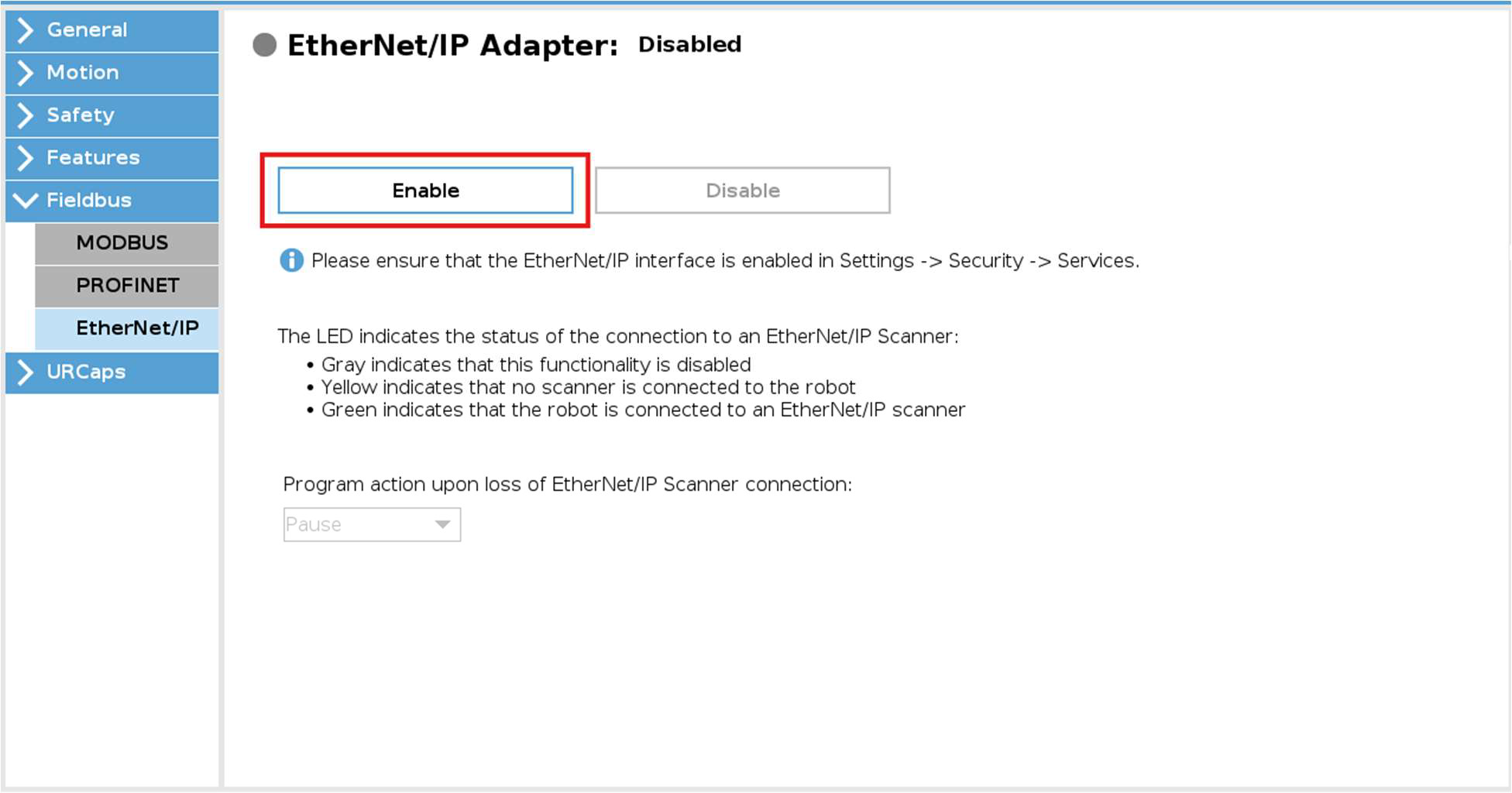
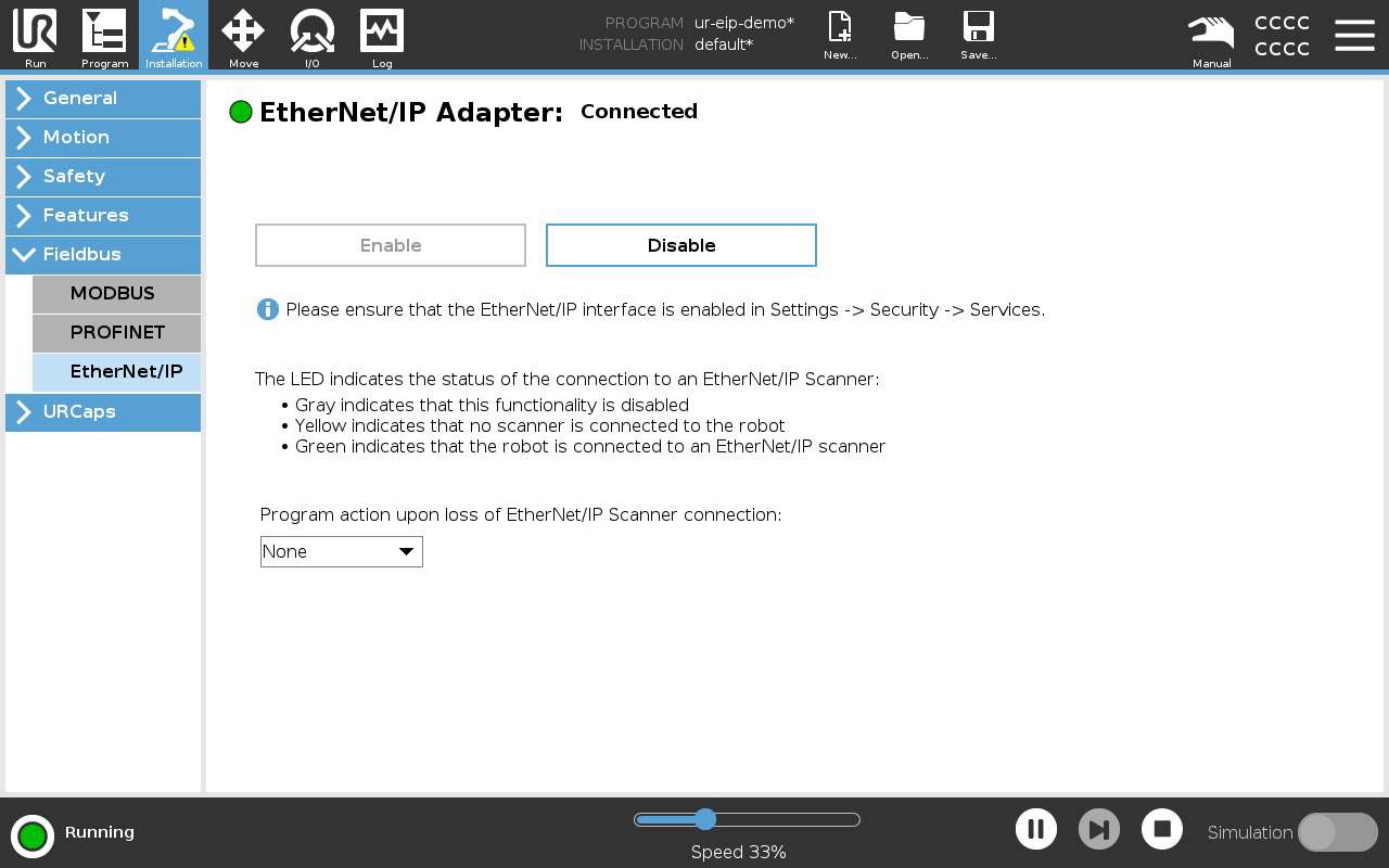
| Robot — Step 3: Enable EtherNet/IP Adapter |
Enable the EtherNet/IP Adapter.
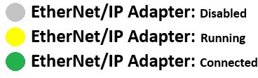
The light next to EtherNet/IP indicates the status of the connection:
|
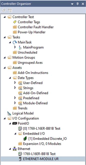
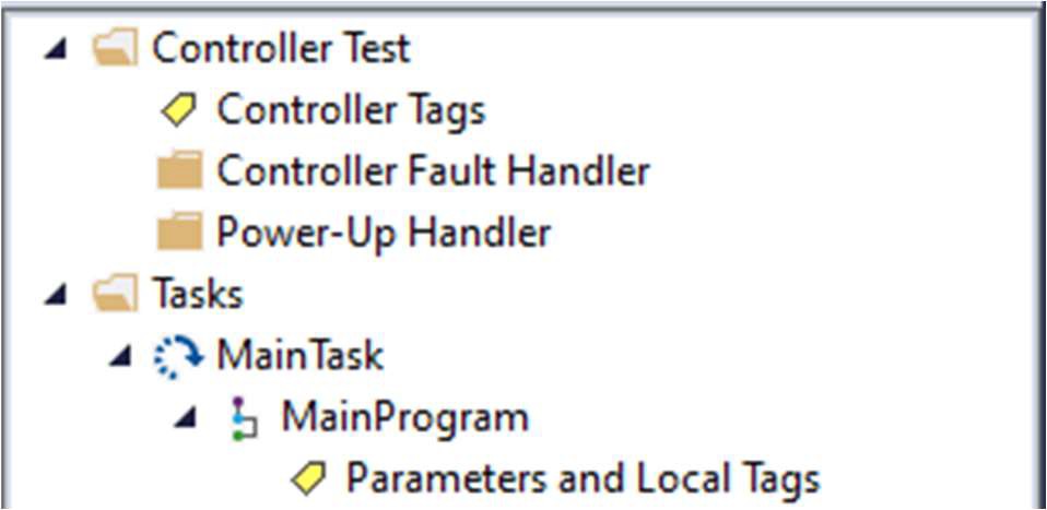
| PLC — Step 4: Open the project in Studio 5000 |
Launch Studio 5000 Logix Designer and open the UR.ACD project file. If your version of Logix Designer is incompatible with the project file (for example older than v.23), you can create a new project and import the user-defined data types from the UR_DataTypes.L5X file. If your version of Studio 5000 is newer you will be prompted to upgrade the program within Logix Designer. The project tree in the Controller Organizer panel should look like this:
|
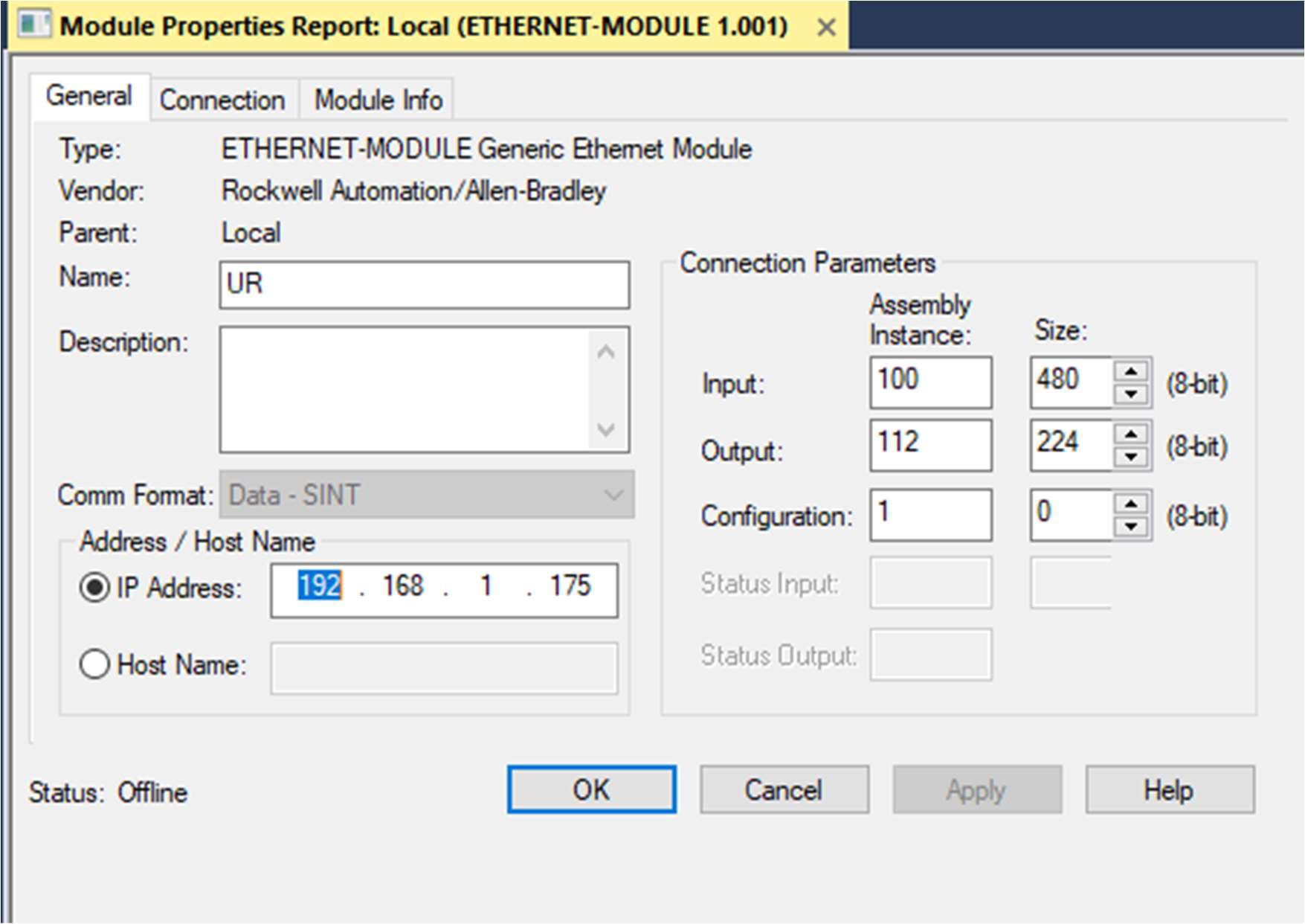
| PLC — Step 5: Configure the UR Ethernet module |
Configure the UR Ethernet Module.
|
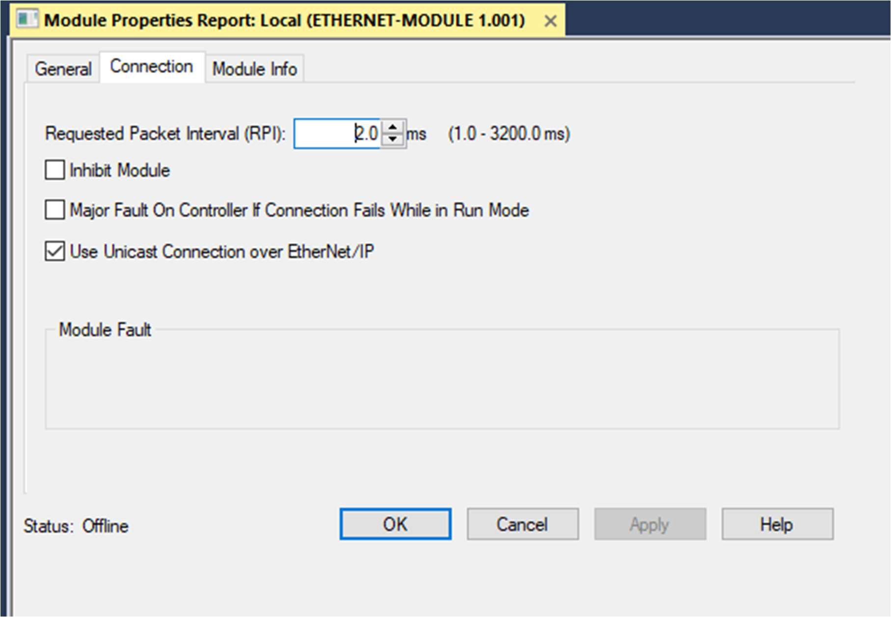
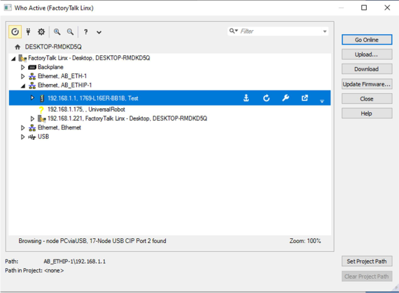
| PLC — Step 6: Connection and download |
|
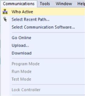
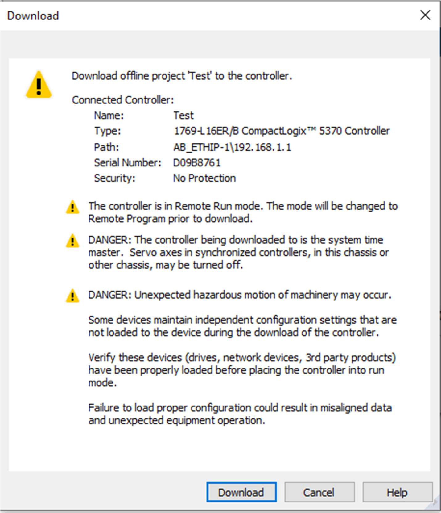
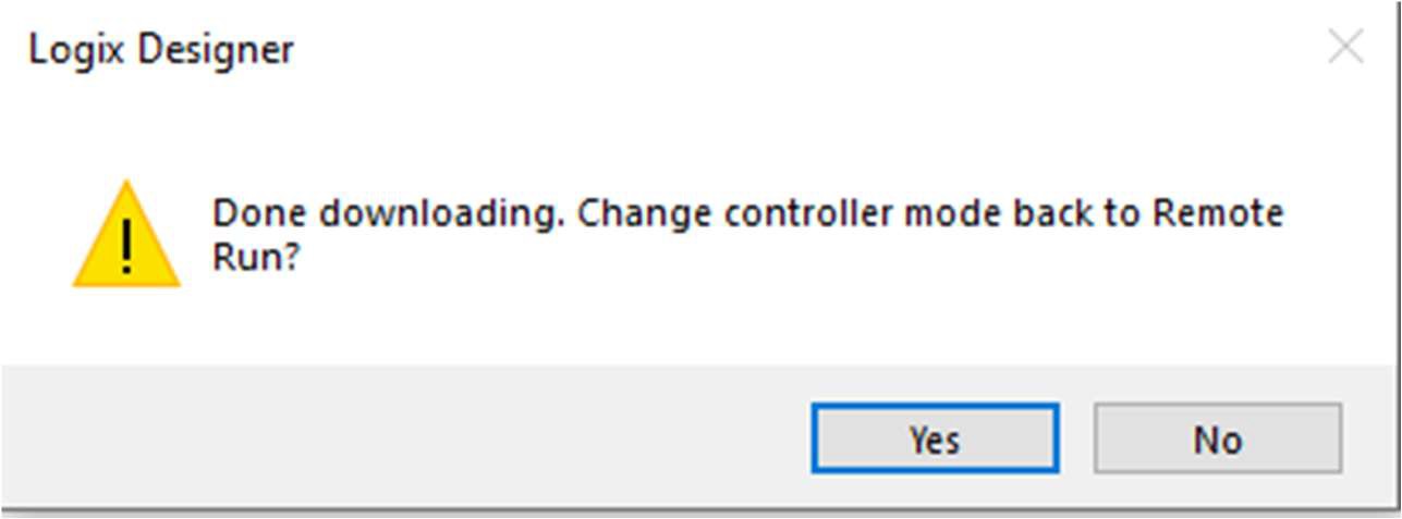
| PLC — Step 7: Download the program to the PLC |
If this is the first time you are going online with your PLC, follow these steps:
|
|
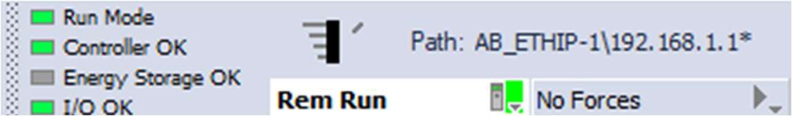
PLC — Step 7: Download the program to the PLC |
|
|
|
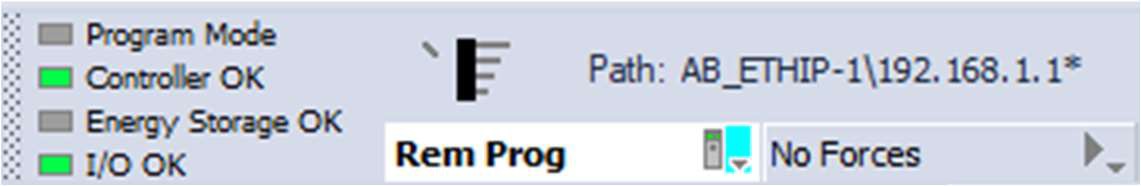
The top left ribbon of Studio 5000 should change from Rem Prog to Rem Run. Ensure the status indicators next to Controller OK and I/O OK are green.
|
|
Robot — Step 8: Verify adapter status |
Navigate back to the EtherNet/IP Adapter page and confirm the status indicator is solid green/Connected.
|
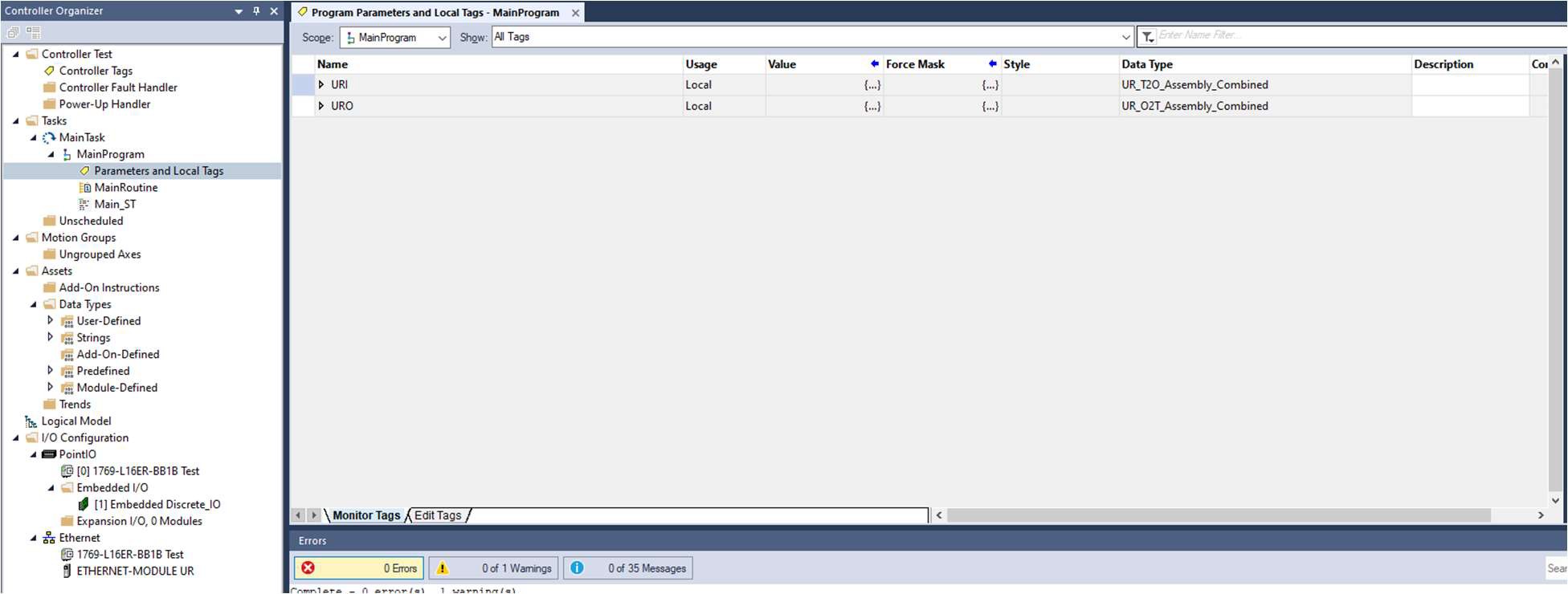
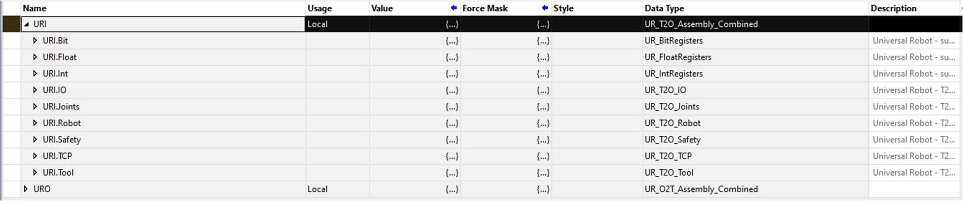
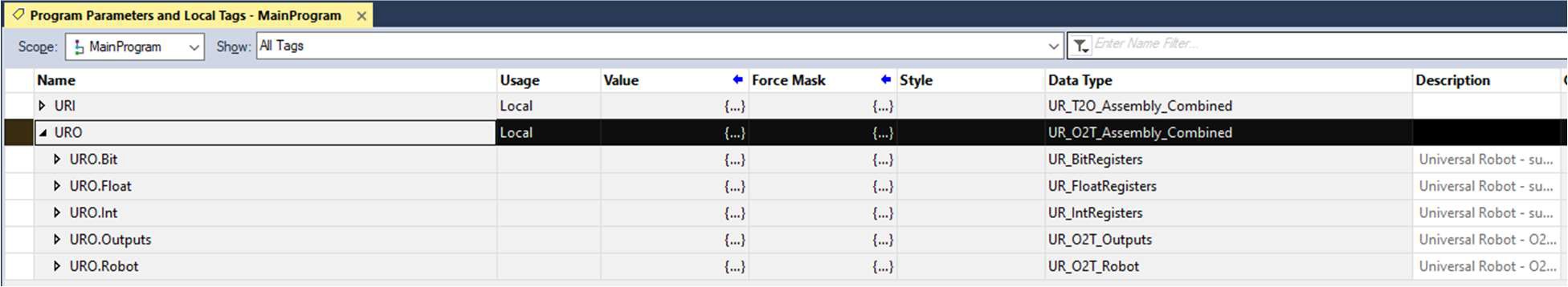
| PLC — Step 9: Parameters and local tags |
If you did not use the demo and will be implementing communication to your own code, you need to enable communication between the robot and the AB PLC. First set up URI and URO in your local or global variables, using the provided User Define Data Types.
|
| PLC — Step 10: CPS (synchronous copy file) |
Setup the CPS (Synchronous Copy File) between the PLC and the robot under the Main Task, MainProgram routine.
|
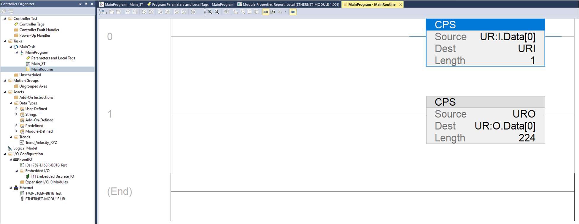
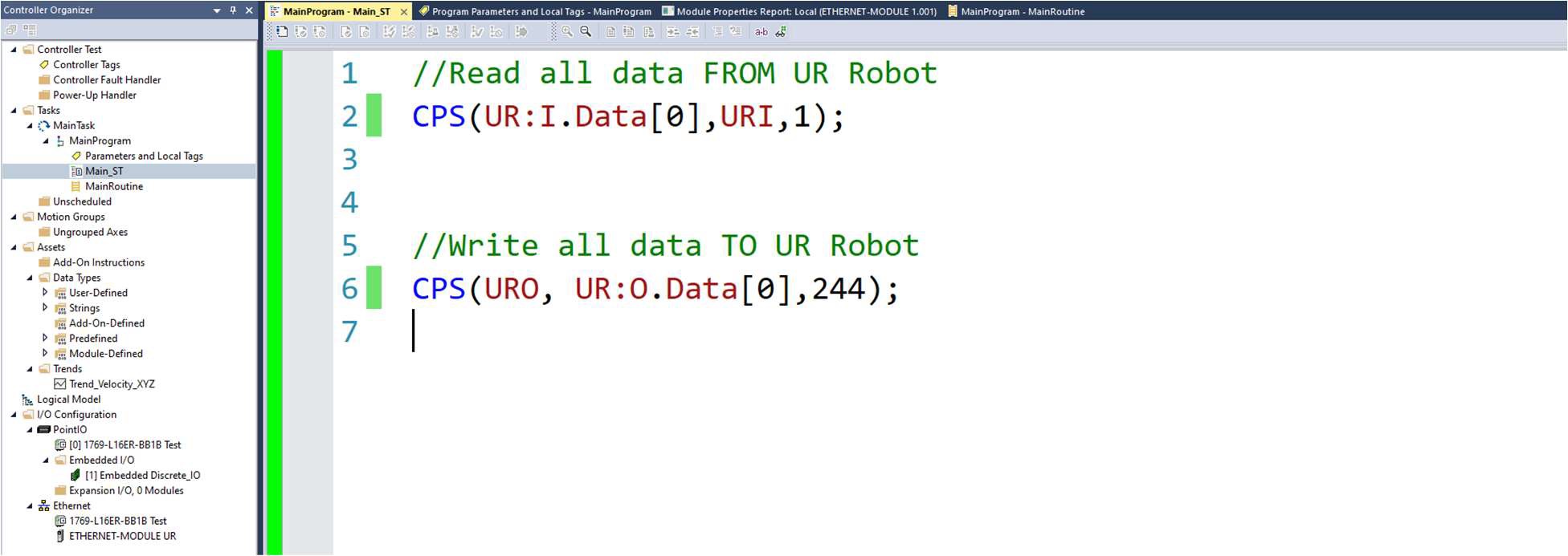
| Example of Ladder and Structured Text |
See this example of Ladder and Structured Text: Both accomplish the same thing and only one is needed.
|
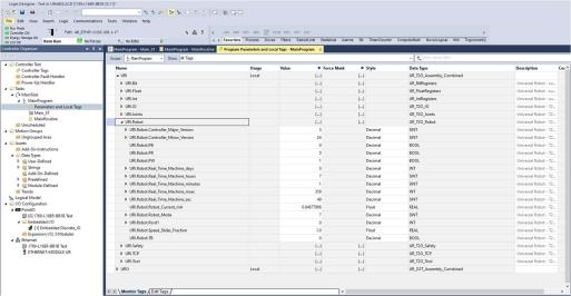
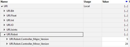
| PLC — Step 11: Inspect live values |
Return to the Parameters and Local tags page to inspect live values sent from the robot. Expand URI, URI.Robot. The Values column will be dynamically changing.
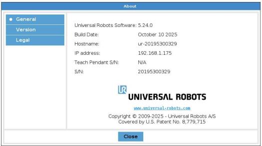
The first two fields,
Confirm this is accurate by comparing to the software version number on the robot.
|