Alternate demo
| Description |
This alternate demo is provided to show a basic example of how to communicate between the PLC and Robot using the I/O Setup page on the Installation Tab to define variable names to specific registers. The PLC program remains the same as in the main Demo, but the ur-eip-demo.urp program must be modified.
|
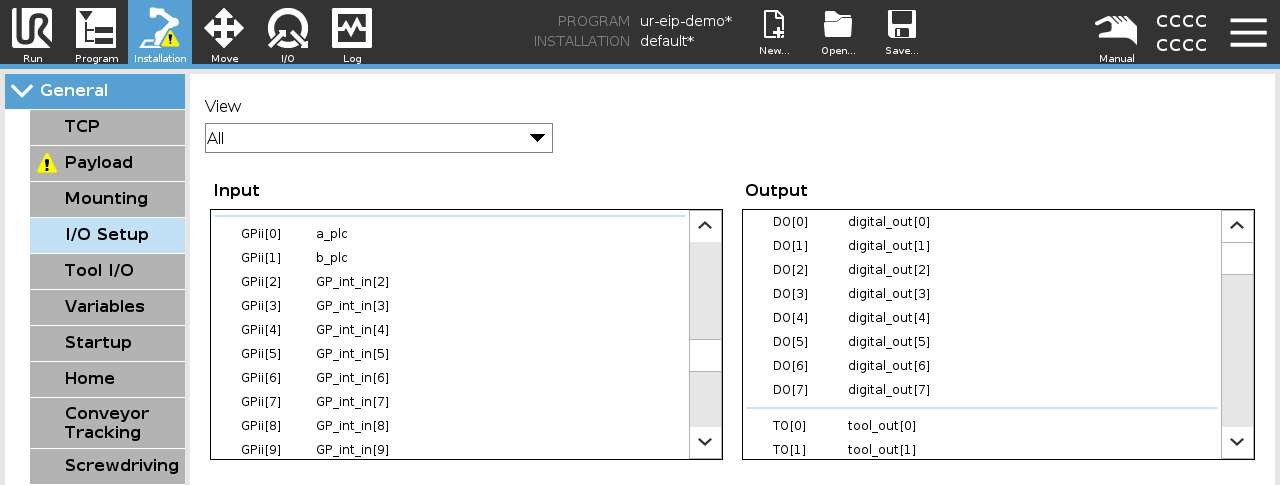
| Robot — Step 1: I/O Setup — input registers |
1. Navigate to the I/O Setup page in the Installation file. Scroll down in the Input panel and locate the GP_int_in[0] and GP_int_in[1] registers. Select each register and rename these to desired Robot Variable names, in the screenshot below “a_plc” and “b_plc” have been assigned to the input registers.
|
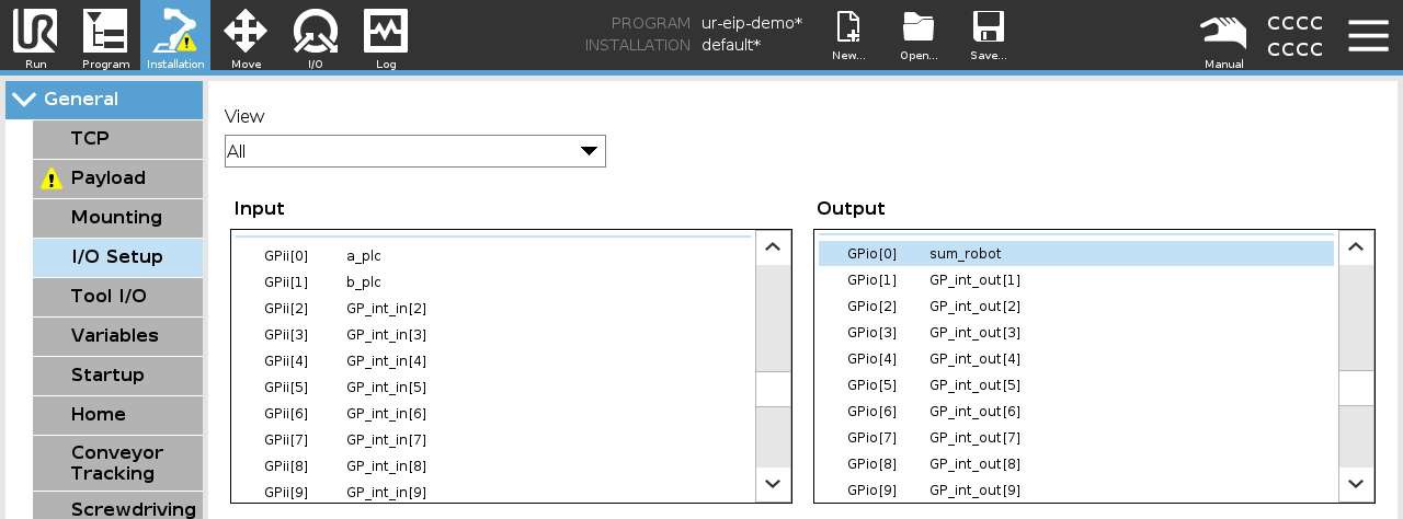
| Robot — Step 2: I/O Setup — output registers |
Complete the same process in the Output panel, locate GPio[0] and rename. In the example below “sum_robot” was used. These variables will now be available in of your Robot Program.
|
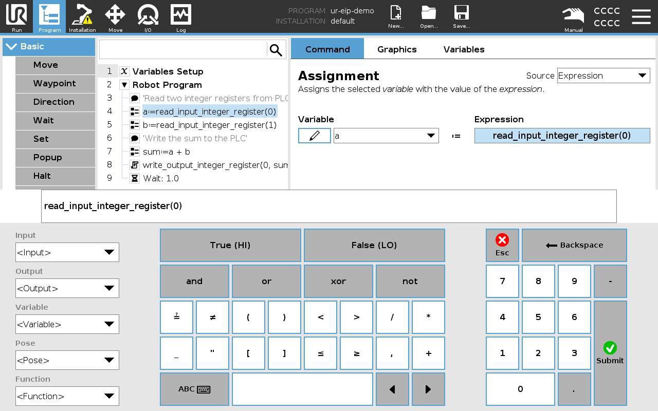
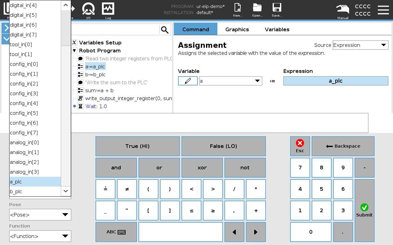
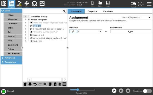
| Robot — Step 3: Program — assignment expressions |
Navigate to the Program Tab, and select Line 4. From the Assignment Node Command Tab, select the Expression and navigate to Inputs on the expression editor window.
|
|
Replace
|
|
Your program tree should match the documentation. Complete the same steps and change
|
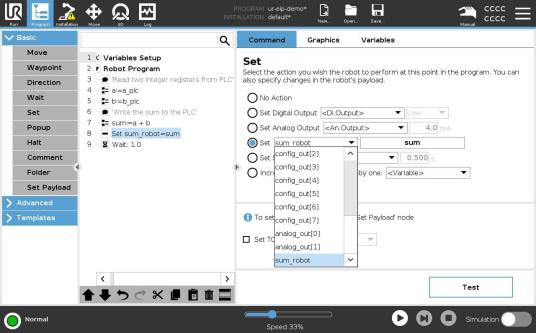
| Robot — Step 4: Set node for output |
4. Replace the Script Command on Line 8 of the robot program with a Set node. From the Command Tab of the Set Node, select the Output variable from the Installation Tab (sum_robot) and then select the name of the variable that contains the sum of the two integers being received by the Robot.
|