Joint Move
| 描述 |
The Joint Move is a move command node that supports Motion Profiles. The command creates a movement from point A to point B that is optimal for the robot. 该移动路径可能不是 A 和 B 之间的直线,但对于关节的起始位置和关节的结束位置来说是最优的。 Joint Move makes movements that are calculated in the robot arm joint space. 与此同时,关节受控完成移动。 这种移动类型会让工具沿着一条曲线路径前进。
|
|
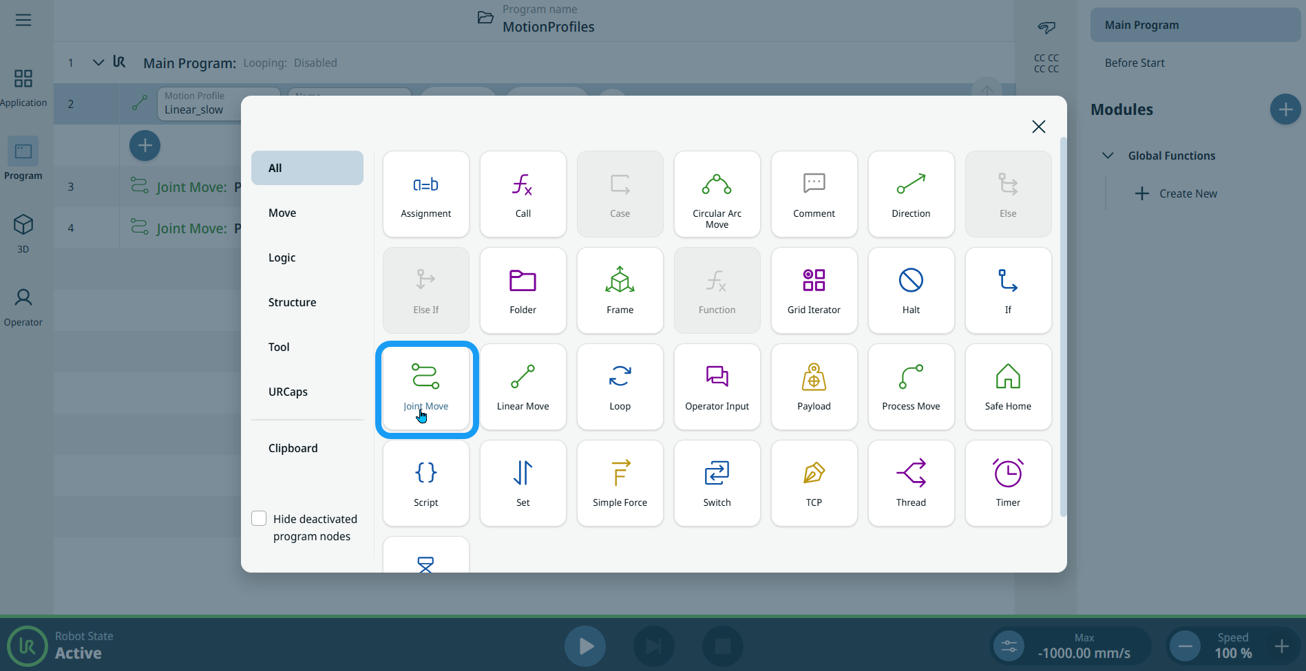
To access Joint Move command |
|
|
|
|
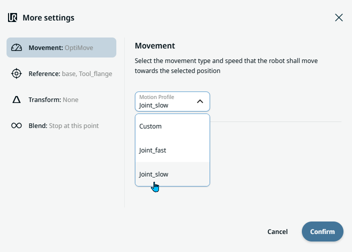
| 移动节点上的运动配置文件标签 |
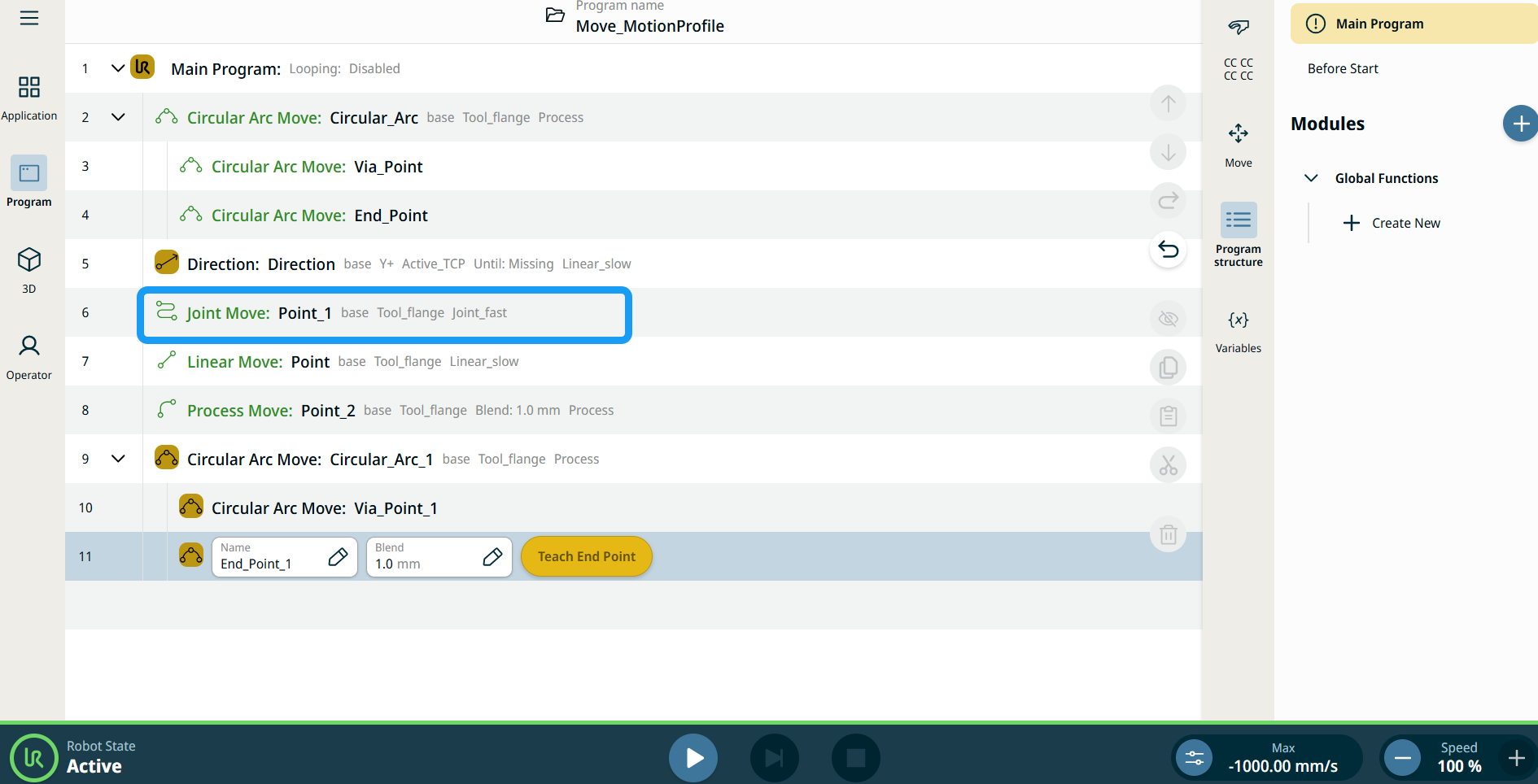
程序树中所有与移动相关的命令节点都会显示与每个节点关联的运动配置文件。 利用此功能,用户可以查看移动节点上的所选运动配置文件。 此功能在以下命令节点实现: 带有自定义运动配置文件的移动节点将显示速度和加速度值,而不显示运动配置文件。 |
|
|
|
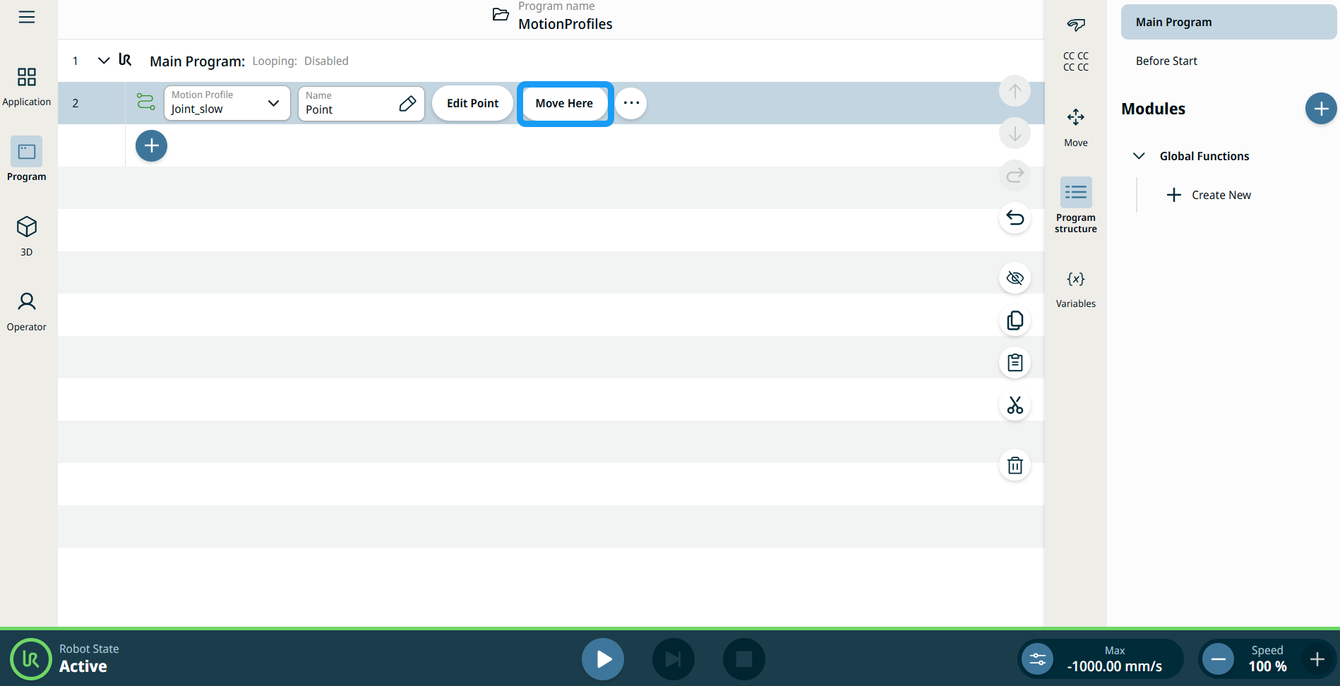
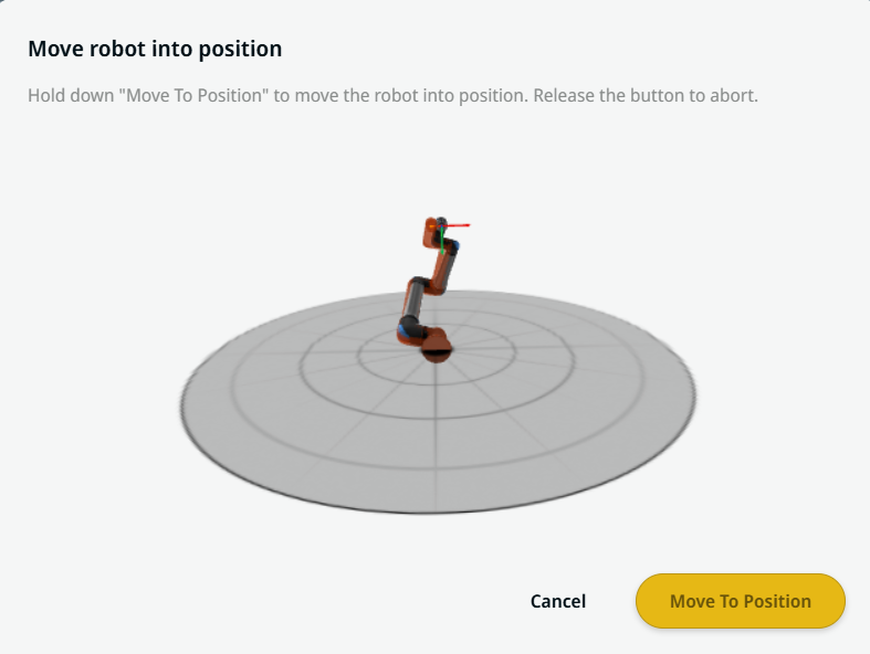
| 使用“移至此处”按钮 |
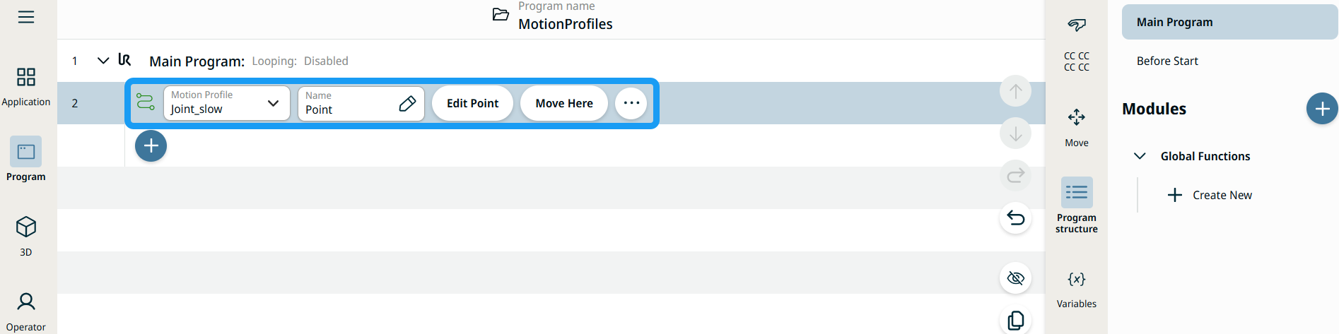
移至此处按钮会出现在Linear Move和Joint Move命令中。 借助此功能,您可以直接从程序树移动到路点的位置。 按下移至此处按钮会打开“将机器人移动就位”对话框。 此按钮在路点已示教的情况下显示,且仅会在机器人状态为正常或缩减模式时启用。
|
| Movement setting |
|
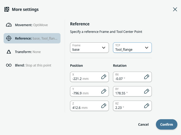
| Reference setting |
|
| Transform setting |
|
|
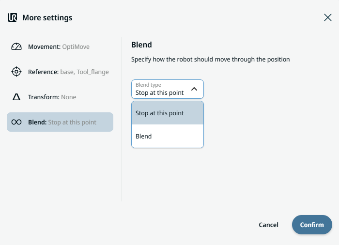
Blend setting |
|