Déplacement Circulaire

Description

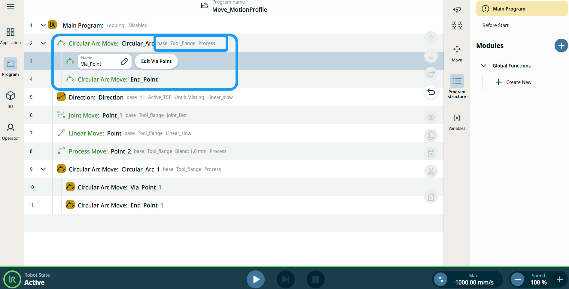
The Circular Arc Move enables you to program the robot to move in a circular motion while keeping the tool orientation either fixed or unconstrained.


To access Circular Arc Move command

  1. Go to the main program screen. Voir Command Nodes.

  2. Tap the Circular Arc Move icon in the Commands toolbox.

    A parent node and two child nodes are inserted into the program tree.

    • First child node = Circular Arc Move: Via_Point

    • Second child node = Circular Arc Move: End_point

    The node has three editable fields and a More button for advanced options.


The three editable fields are:

  • Nom

    A name for referencing the node.

  • Vitesse

    The robot speed during the move.

  • Accélération

    The robot acceleration during the move.

  1. Tap the Name field, and three tabs appear:

    • Valeur

    • Variable

    • Expression

  2. Enter the data in each tab and tap Confirm. See Value-Variable-Expression Tabs.

  3. Tap the Speed field, and three tabs appear:

    • Valeur

    • Variable

    • Expression

  4. Repeat step 4.

  5. Tap the Acceleration field, and three tabs appear:

    • Valeur

    • Variable

    • Expression

  6. Repeat step 4.

Étiquettes du profil de mouvement sur les nœuds de déplacement

Tous les nœuds de commandes liés au mouvement dans l'arborescence du programme affichent le profil de mouvement associé à chaque nœud. Cette fonction permet aux utilisateurs de voir le profil de mouvement sélectionné sur un nœud de déplacement. Cette fonctionnalité est implémentée sur les nœuds de commande suivants :

Les nœuds de mouvement avec le profil de mouvement personnalisé affichera les valeurs de la vitesse et de l'accélération au lieu du profil de mouvement.


To access More settings

Tap the More button, and the More settings screen appears.

On the left side, you see four advanced options:

  • Orientation

  • Mouvement

  • Référence 

  • Transformation


To use Orientation

  1. Tap Orientation.

    On the right side, two buttons are provided:

    • Contraint

    • Non contraint

  2. Tap Fixed when you want the start point only to be used to define the tool orientation, and Confirm.

  3. Tap Unconstrained when you want the start point to transform to the endpoint to define tool orientation and Confirm.

    Note: A diagram shows the difference between the two endpoints when you choose unconstrained.


To use Movement

  1. Tap Movement.

    Two fields appear:

    • Vitesse

    • Accélération

  2. Tap the Speed field, and three tabs appear:

    • Valeur

    • Variable

    • Expression

  3. Enter the data in each tab and tap Confirm. See Value-Variable-Expression Tabs.

  4. Tap the Acceleration field, and three tabs appear:

    • Valeur

    • Variable

    • Expression

  5. Enter the data in each tab and tap Confirm. See Value-Variable-Expression Tabs.


To use Reference

  1. Tap Reference, and two editable Frame and TCP fields appear.

    Tap the Frame field, and four options are selectable:

    • monde

    • base

    • flange

    • tcp

  2. Tap the TCP field, and two options are selectable:

    • Tool_flange

    • TCP_Actif

  3. In the Position column, tap X, Y, Z fields to enter the value, and Confirm.

  4. In the Rotation column, tap RX, RY, RZ fields to enter the value, and tap Confirm.


To use Transform

  1. Tap Transform.

  2. Tap the Pose field to specify how the position needs to be transformed and Confirm.


To use Circular Arc Move: Via_point

  1. Tap the Circular Arc Move: Via_Point node and two fields appear:

    • Nom

    • Teach Via Point

  2. Tap the Name field, and three tabs appear:

    • Valeur

    • Variable

    • Expression

  3. Enter the data in each tab and tap Confirm. See Value-Variable-Expression Tabs.

  4. Tap Teach Via Point.

    The 3D viewer screen of the robot appears. (See Déplacement articulaire and Déplacement linéaire for details of use.)


To use Circular Arc Move: End_Point

  1. Tap the Circular Arc Move: End_Point node, and three fields appear:

    • Nom

    • Lissage

    • Teach Via Point

  2. Tap the Name field, and three tabs appear:

    • Valeur

    • Variable

    • Expression

  3. Enter the data in each tab and tap Confirm. See Value-Variable-Expression Tabs.

  4. Tap the Blend field, and three tabs appear:

    • Valeur

    • Variable

    • Expression

  5. Repeat step 3.

  6. Tap Teach End Point.

    The 3D viewer screen of the robot appears. (See Déplacement articulaire and Déplacement linéaire for details of use.)