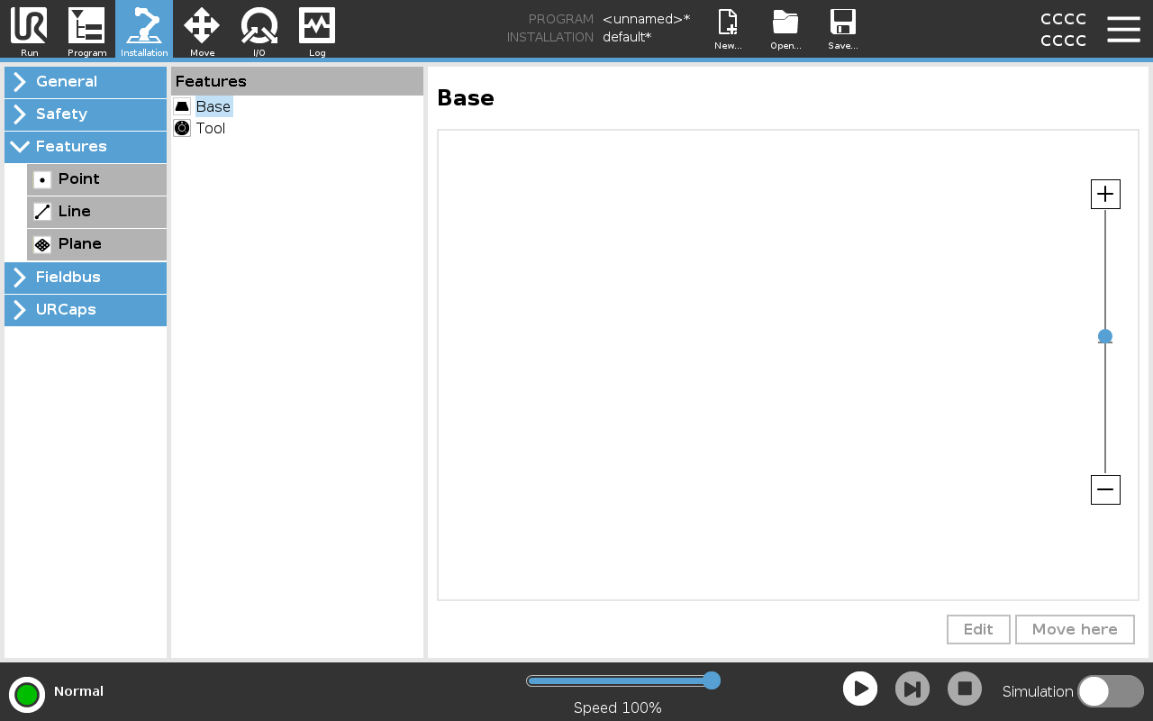
Features

Description

A Feature represents an object defined by a six dimensional pose (position and orientation) relative to the robot base. You can name a feature for future reference.

Some subparts of a robot program consist of movements executed relative to specific objects other than the base of the robot arm. These objects can be tables, other machines, workpieces, vision systems, blanks, or boundaries existing around the robot arm.

The robot includes two predefined features, listed below, with poses defined by the configuration of the robot arm itself:

  • The Base feature is located with origin in the centre of the robot base.

  • The Tool feature is located with origin in the centre of the current TCP.


Base feature


Tool feature


Detail

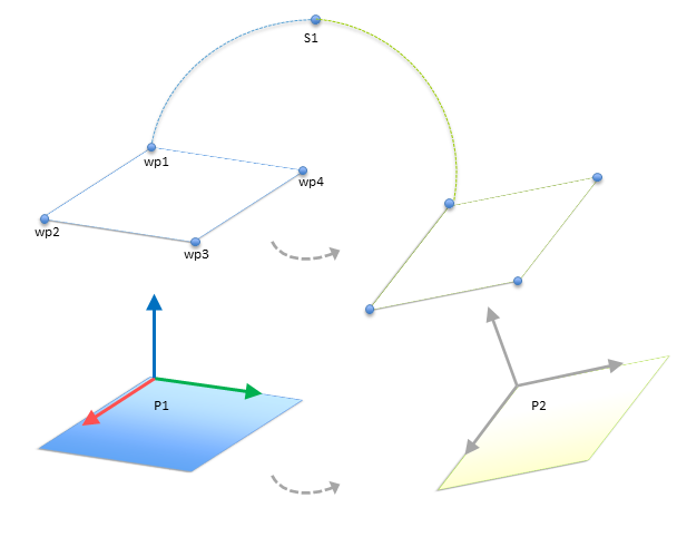
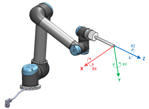
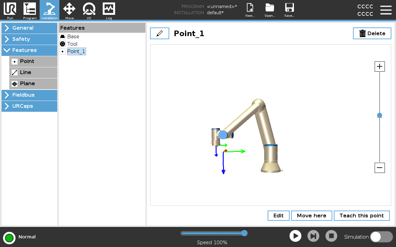
Use the Point feature, Line feature and/or Plane feature to define a feature pose.

These features are positioned through a method that uses the current pose of the TCP in the work area. So you can teach feature locations using Freedrive , or "jogging" to move the robot to the desired pose.

Selecting a feature depends on the type of object being used and the precision requirements. Use the Line feature and Plane feature where possible as they are based on more input points. More input points mean higher precision.


For example, you can accurately define the direction of a linear conveyor, by defining two points of a Line feature with as much physical separation as possible. You can also use the Point feature to define a linear conveyor, however, you must point the TCP in the direction of the conveyor's movement.

Using more points to define the pose of a table means that the orientation is based on the positions rather than the orientation of a single TCP. A single TCP orientation is harder to configure with high precision.
For more on adding features, see (sections: Adding a Point) and (Plane Feature).


Using a Feature

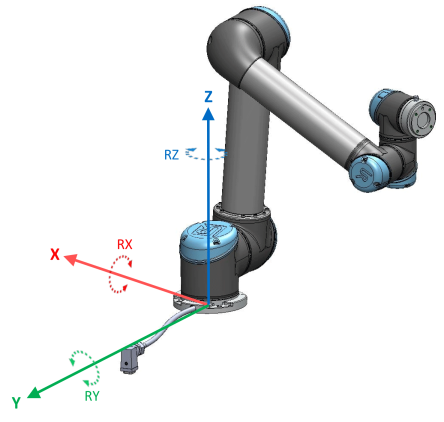
You can refer to a feature defined the installation from the robot program, to relate robot movements (e.g. MoveJ, MoveL and MoveP commands) to the feature (see section Move).

This allows for easy adaptation of a robot program when for example: there are multiple robot stations, when an object is moved during program runtime, or when an object is permanently moved in the scene. Adjusting the feature of an object, adjusts all program movements relative to the object accordingly.

For further examples, see sections: (Example: Manually Updating a Feature to Adjust a Program) and (Example: Dynamically Updating a Feature Pose). When a feature is chosen as a reference, the Move Tool buttons for translation and rotation operate in the selected feature space (see Move Tab) and (To use the Move Tool arrows), reading of the TCP coordinates. For example, if a table is defined as a feature and is chosen as a reference in the Move Tab, the translation arrows (i.e., up/down, left/right, forward/backward) move the robot in these directions relative to the table. Additionally, the TCP coordinates will be in the frame of the table.
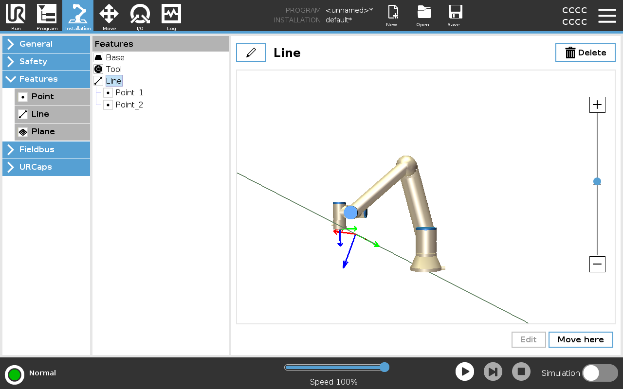
  • In the Features tree you can rename a Point, Line or Plane by tapping the pencil button.

  • In the Features tree you can delete a Point, Line or Plane by tapping the Delete button.


Using Move here

Tap Move here to move the robot arm towards the selected feature. At the end of this movement, the coordinate systems of the feature and the TCP will coincide.

Move here is disabled if the robot arm cannot reach the feature.


Point feature

The point feature defines a safety boundary or a global home configuration of the Robot arm. The point feature pose is defined as the position and orientation of the TCP.

Adding a Point
  1. In Installation, select Features.

  2. Under Features select Point.


Line feature


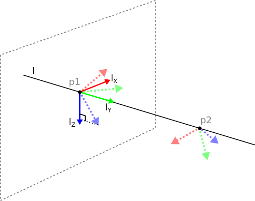
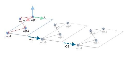
The line feature defines lines that the robot needs to follow. (e.g., when using conveyor tracking). A line l is defined as an axis between two point features p1 and p2 as shown in figure Features.

Adding a Line

  1. In Installation, select Features.

  2. Under Features select Line.


Here you can see the axis directed from the first point towards the second point, constitutes the y-axis of the line coordinate system. The z-axis is defined by the projection of the z-axis of p1 onto the plane perpendicular to the line. The position of the line coordinate system is the same as the position of p1.


Plane Feature Select the plane feature when you need a frame with high precision: e.g., when working with a vision system or doing movements relative to a table.
Adding a plane
  1. In Installation, select Features.

  2. Under Features select Plane.

Teaching a plane

When you press the plane button to create a new plane, the on-screen guide assists you creating a plane.

  1. Select Origo

  2. Move robot to define the direction of the positive x-axis of the plane

  3. Move robot to define the direction of the positive y-axis of the plane

The plane is defined using the right hand rule so the z- axis is the cross product of the x-axis and the y-axis, as illustrated below.

You can re-teach the plane in the opposite direction of the x-axis, if you want that plane to be normal in the opposite direction.

Modify an existing plane by selecting Plane and pressing Modify Plane. You will then use the same guide as for teaching a new plane.


Example: Manually Updating a Feature to Adjust a Program

Consider an application where multiple parts of a robot program is relative to a table. The figure below illustrates the movement through waypoints from wp1 to wp4.

Robot Program
    MoveJ
        S1
    MoveL # Feature: P1_var
        wp1
        wp2
        wp3
        wp4

14.1:  Simple program with four waypoints relative to a feature plane manually updated by changing the feature

14.2:  

The application requires the program to be reused for multiple robot installations where the position of the table varies slightly. The movement relative to the table is identical. By defining the table position as a feature P1 in the installation, the program with a MoveL command configured relative to the plane can be easily applied on additional robots by just updating the installation with the actual position of the table.

The concept applies to a number of Features in an application to achieve a flexible program can solve the same task on many robots even though if other places in the work space varies between installations.


Example: Dynamically Updating a Feature Pose

Consider a similar application where the robot must move in a specific pattern on top of a table to solve a particular task.

A MoveL command with four waypoints relative to a plane feature

Robot Program
    MoveJ
        wp1
    y = 0.01
    o = p[0,y,0,0,0,0]
    P1_var = pose_trans(P1_var, o)
    MoveL # Feature: P1_var
        wp1
        wp2
        wp3
        wp4

14.3:  Applying an offset to the plane feature

14.4:  

Robot Program
    MoveJ
        S1
    if (digital_input[0]) then
        P1_var = P1
    else
        P1_var = P2
    MoveL # Feature: P1_var
        wp1
        wp2
        wp3
        wp4

14.5:  Switching from one plane feature to another

14.6:  

The movement relative to P1 is repeated a number of times, each time by an offset o. In this example the offset is set to 10 cm in the Y-direction, offsets O1 and O2). This is achieved using pose_add() or pose_trans() script functions to manipulate the variable. It is possible to switch to a different feature while the program is running instead of adding an offset. This is shown in the example. See the figure where the reference feature for the MoveL command P1_var can switch between two planes P1 and P2.