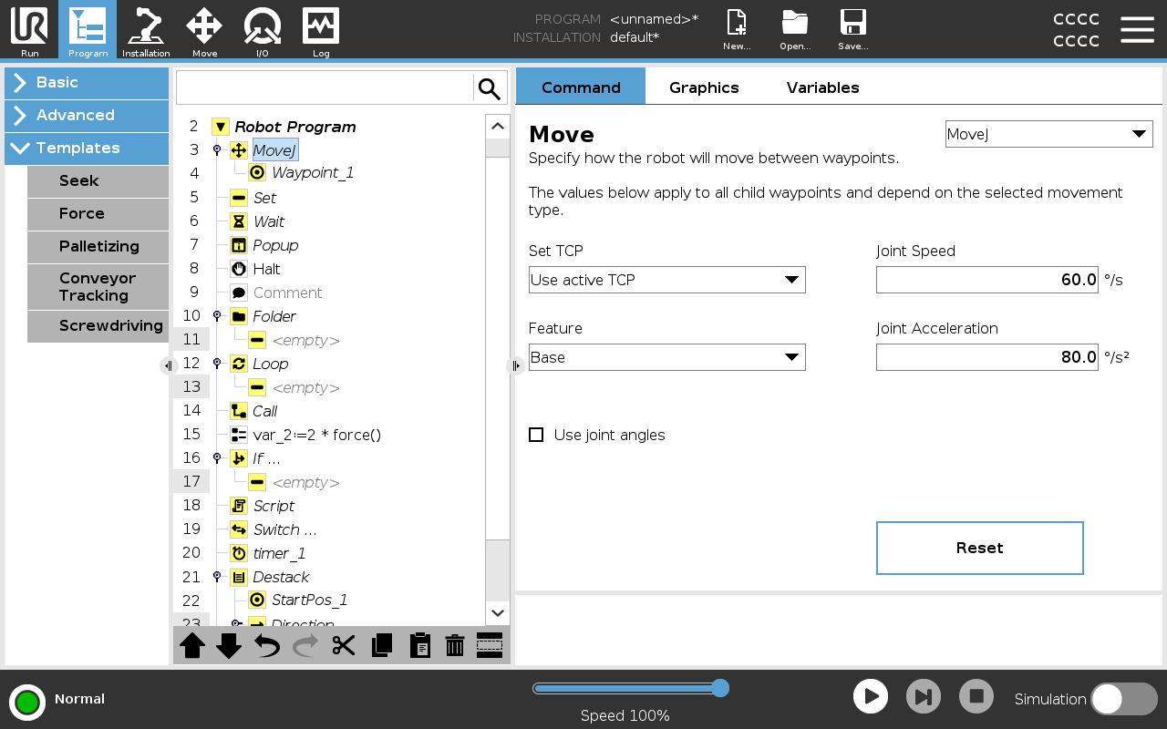
Move

Description

The Move command allows the robot to move from point A to point B.

How the robot moves is important to the task the robot is performing.

When you add a Move to your program tree, the Move pane appears to the right of the screen.


The Movecommand controls the robot's motion via waypoints.

Waypoints are automatically added when you add Move commands to a program.

Read more about Waypoints.

You can also use Moves to set acceleration and speed for the robot arm's movement between waypoints.


See the following sections about using a Move:

The robot moves using four Move commands. See the Move command types below:


MoveJ

The MoveJ command creates a movement from point A to point B that is optimal for the robot.

The movement may not be a direct line between A and B, but optimal for the start position of the joints and the end position of the joints.

Add a MoveJ command
  1. In your robot program, select the place where you wish to add a Move.

  2. Under Basic, tap Move to add a waypoint to the robot program together with a Move node.

  3. Select the move node.

  4. Select the MoveJ in the drop-down menu.

Detail

MoveJ makes movements that are calculated in the robot arm joint space. Joints are controlled to finish their movements at the same time. This movement type results in a curved path for the tool to follow. The shared parameters that apply to this movement type are the maximum joint speed and joint acceleration, specified in deg/s and deg/s2, respectively. If it is desired to have the robot arm move fast between waypoints, disregarding the path of the tool between those waypoints, this movement type is the preferable choice.


MoveL

The MoveL command creates a movement that is a direct line from point A and point B.


Add a MoveL command
  1. In your Robot Program, select the place where you wish to add a Move.

  2. Under Basic, tap Move to add a waypoint to the robot program together with a Move node.

  3. Select the move node.

  4. Select the MoveL from the drop-down menu.

Detail

MoveL moves the Tool Center Point (TCP) linearly between waypoints. This means that each joint performs a more complicated motion to keep the tool on a straight line path. The shared parameters that can be set for this movement type are the desired tool speed and tool acceleration specified in mm/s and mm/s2, respectively, and also a feature.


MoveP

The MoveP command creates a movement with a constant speed between the waypoints.

Blend between waypoints is enabled to ensure constant speed. (See Blending).

Add a MoveP command
  1. In your Robot Program, select the place where you wish to add a Move.

  2. Under Basic, tap Move to add a waypoint to the robot program together with the Move node.

  3. Select the move node.

  4. Select the MoveP from the drop-down menu.

Detail

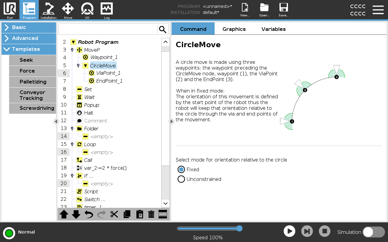
MoveP moves the tool linearly with constant speed with circular blends, and is intended for some process operations, like gluing or dispensing. The size of the blend radius is by default a shared value between all the waypoints. A smaller value will make the path turn sharper whereas a higher value will make the path smoother. While the robot arm is moving through the waypoints with constant speed, the robot control box cannot wait for either an I/O operation or an operator action. Doing so might stop the robot arm’s motion, or cause a robot stop.


MoveCircle

The MoveCircle command creates a circular movement, by creating a half circle.

You can only add CircleMove via a MoveP command.

Add a MoveCircle command
  1. In your Robot Program, select the place where you wish to add a Move.

  2. Under Basic, tap Move.

    A waypoint is added to the robot program together with the Move node.

  3. Select the move node.

  4. Select the MoveP from the drop-down menu.

  5. Tap Add circle move

  6. Select the orientation mode.

Detail

The robot starts the circular movement from its current position, or start point, and moves through a ViaPoint specified on the circular arc, to an EndPoint that completes the circular movement.

A mode is used to calculate tool orientation, through the circular arc.

The mode can be:

  • Fixed: only the start point is used to define the tool orientation.

  • Unconstrained: the start point transforms to the EndPoint to define tool orientation.