Move Tab

Description

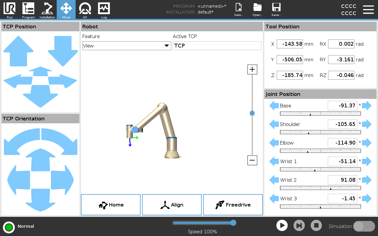
Use the Move Tab screen to move (jog) the robot arm directly, either by translating/rotating the robot tool, or by moving robot joints individually.


To use the Move Tool arrows

Hold down any of the Move Tool arrows to move the robot arm in the corresponding direction.

  • The Translate arrows (upper) move the tool flange in the direction indicated.

  • The Rotate arrows (lower) change the orientation of the tool in the indicated direction. The rotation point is the Tool Center Point (TCP), i.e.the point at the end of the robot arm that gives a characteristic point on the tool. The TCP is shown as a small blue ball.

Robot

If the current position of the TCP approaches a safety plane, a trigger plane, or the orientation of robot tool is near the tool orientation boundary limit , a 3D representation of the proximate boundary limit is shown. The visualization of boundary limits is disabled during program execution.


Safety planes display in yellow and black with an arrow indicating which side of the plane, the robot TCP is allowed to be positioned.


Trigger planes display in blue and green with an arrow indicating the side of the plane, where the Normal mode limits are active.


The tool orientation boundary limit is visualized with a spherical cone together with a vector indicating the current orientation of the robot tool. The inside of the cone represents the allowed area for the tool orientation (vector).

When the robot TCP is no longer in proximity of the limit, the 3D representation disappears. If the TCP is in violation or very close to violating a boundary limit, the visualization of the limit turns red.

Feature

Under Feature, you can define how to control the robot arm relative to View, Base or Tool features. For the best feel for controlling the robot arm you can select the View feature, then use Rotate arrows to change the viewing angle of the 3D image to match your view of the real robot arm.


Active TCP

In the Robot field, under Active TCP, the name of the current active Tool Center Point (TCP) is displayed.


Home

The Home button accesses the Move Robot into Position screen, where you can hold down the Auto button to move robot into position previously defined under Installation. The Home button’s default setting returns the Robo Arm to an upright position .


Freedrive

The on-screen Freedrive button allows the Robot Arm to be pulled into desired positions/poses.


Align

The Align button allows the Z axis of the active TCP to align to a selected feature.


Tool Position

The text boxes display the full coordinate values of the TCP relative to the selected feature. You can configure several named TCPs (see ). You can also tap Edit pose to access the Pose Editor screen.


Joint Position

The Joint Position field allows you to directly control individual joints. Each joint moves along a default joint limit range from  − 360 to  + 360, defined by a horizontal bar. Once the limit is reached you cannot move a joint any further. You can configure joints with a position range different from the default, this new range is indicated with red zone inside the horizontal bar.


Using Freedrive in the Move tab

The Freedrive button shall only be used in applications if allowed by the risk assessment.

Failure to correctly configure the mounting setting can result in unwanted robot arm movement when you use the Freedrive button.

  • Payload settings and robot mounting settings shall be set correctly before using Freedrive.

  • All personnel shall remain outside the reach of the robot arm, when Freedrive is in use.

Failure to correctly configure the installation settings, can increase the risk of the robot arm falling during Freedrive, due to payload errors.

  • Verify the installation settings are correct (e.g. Robot mounting angle, payload mass and payload center of gravity offset) . Save and load the installation files along with the program.

  • Save and load the installation files along with the program.