Joint Move
| Description |
The Joint Move works in a similar way to Move to command, but it supports Motion Profiles. The command creates a movement from point A to point B that is optimal for the robot. The movement may not be a direct line between A and B, but optimal for the start position of the joints and the end position of the joints. Joint Move makes movements that are calculated in the robot arm joint space. Joints are controlled to finish their movements at the same time. This movement type results in a curved path for the tool to follow.
|
|
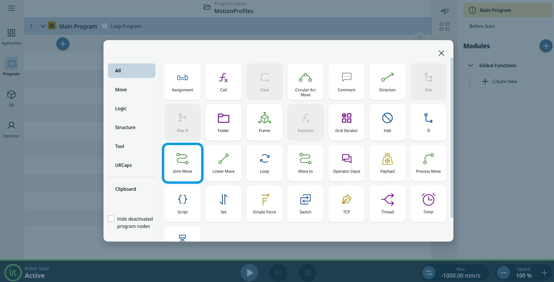
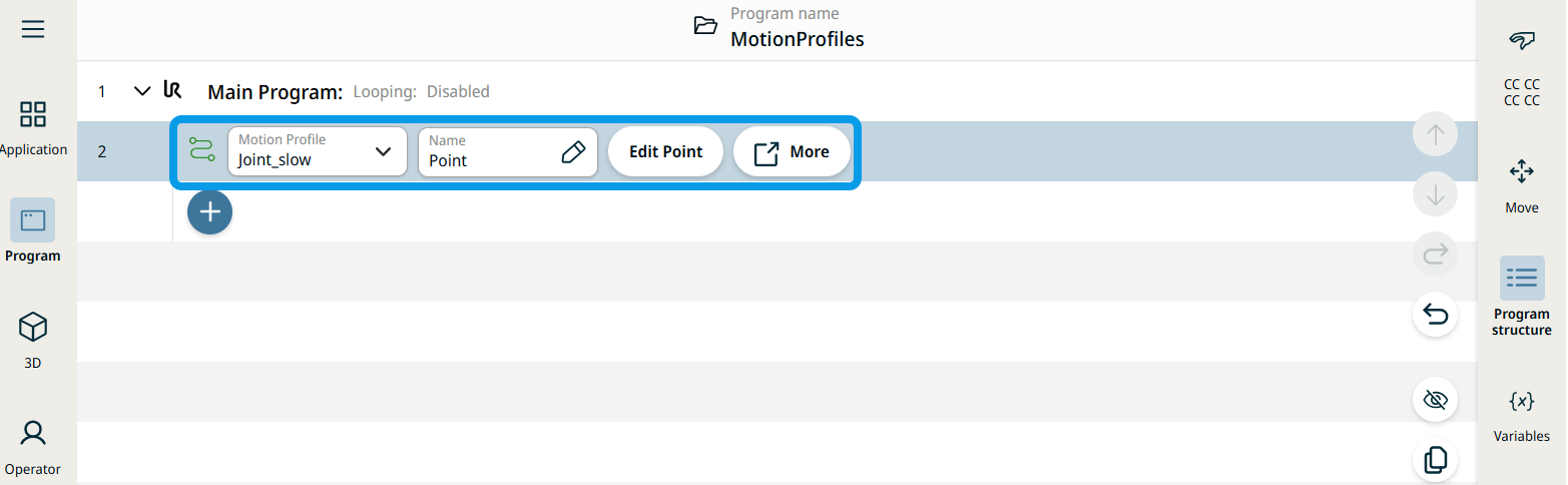
To access Joint Move command |
|
|
|
|
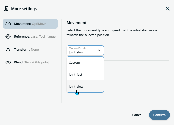
| Movement setting |
|
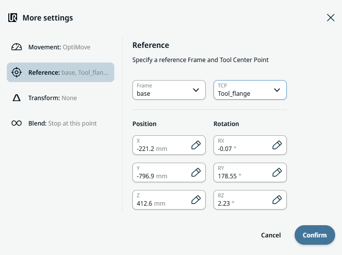
| Reference setting |
|
| Transform setting |
|
|
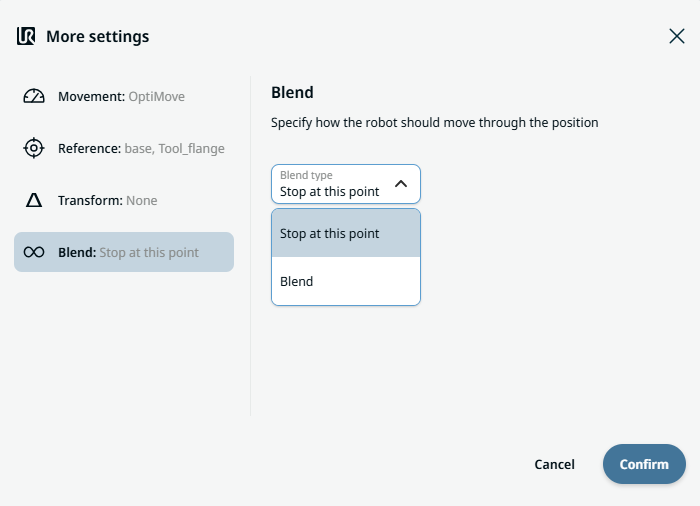
Blend setting |
|