Move To
| Description |
The Move to command allows the robot to move from different points to a given location.
|
| To access Move to command |
|
|
|
|


|
To use Edit Point field |
|

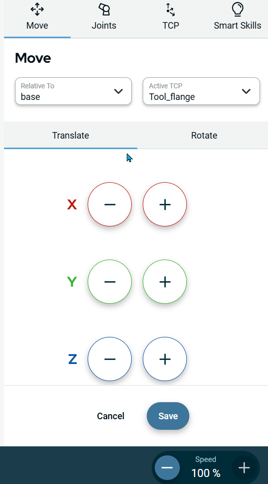
| To use Move |
|
|
|
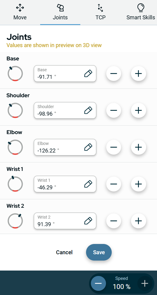
To use Joints |
|
|
You can see the three options to input the values for the six parts of the robot arm:
|
|
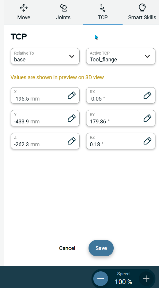
To use TCP |
|
|
|
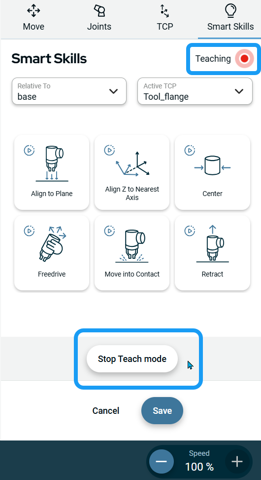
To use Smart Skills |
|
Six smart skills functionalities are given for you to move the robot:
|
|
To use More option |
|
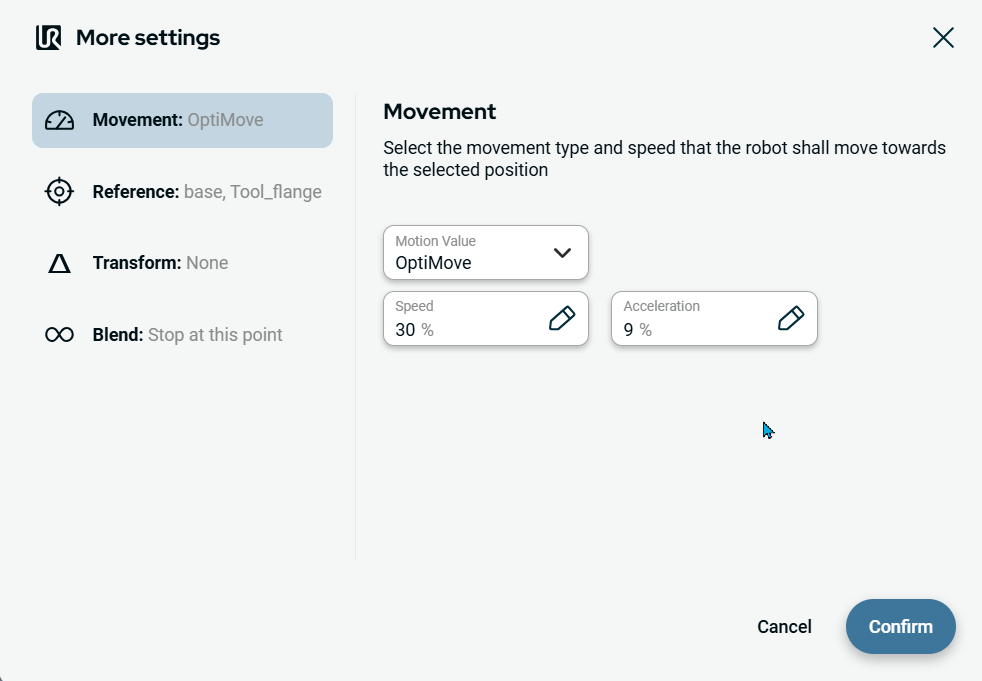
| To use Movement setting |
|

| To use Reference setting |
|

| To use Transform setting |
|
| To use Blend setting |
|
