Linear Move
| Description |
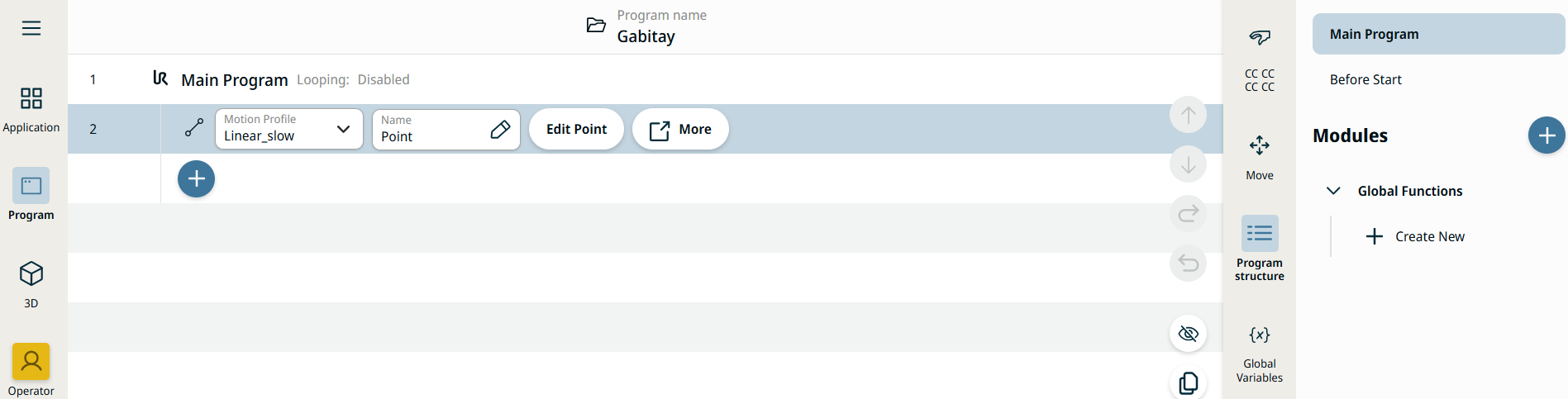
The Linear Move command behaves in a similar way to the existing Move To node but supports Motions Profiles. This command creates a movement that is a direct line from point A and point B. It moves the Tool Center Point (TCP) linearly between waypoints. This means that each joint performs a more complicated motion to keep the tool on a straight line path.
|
|
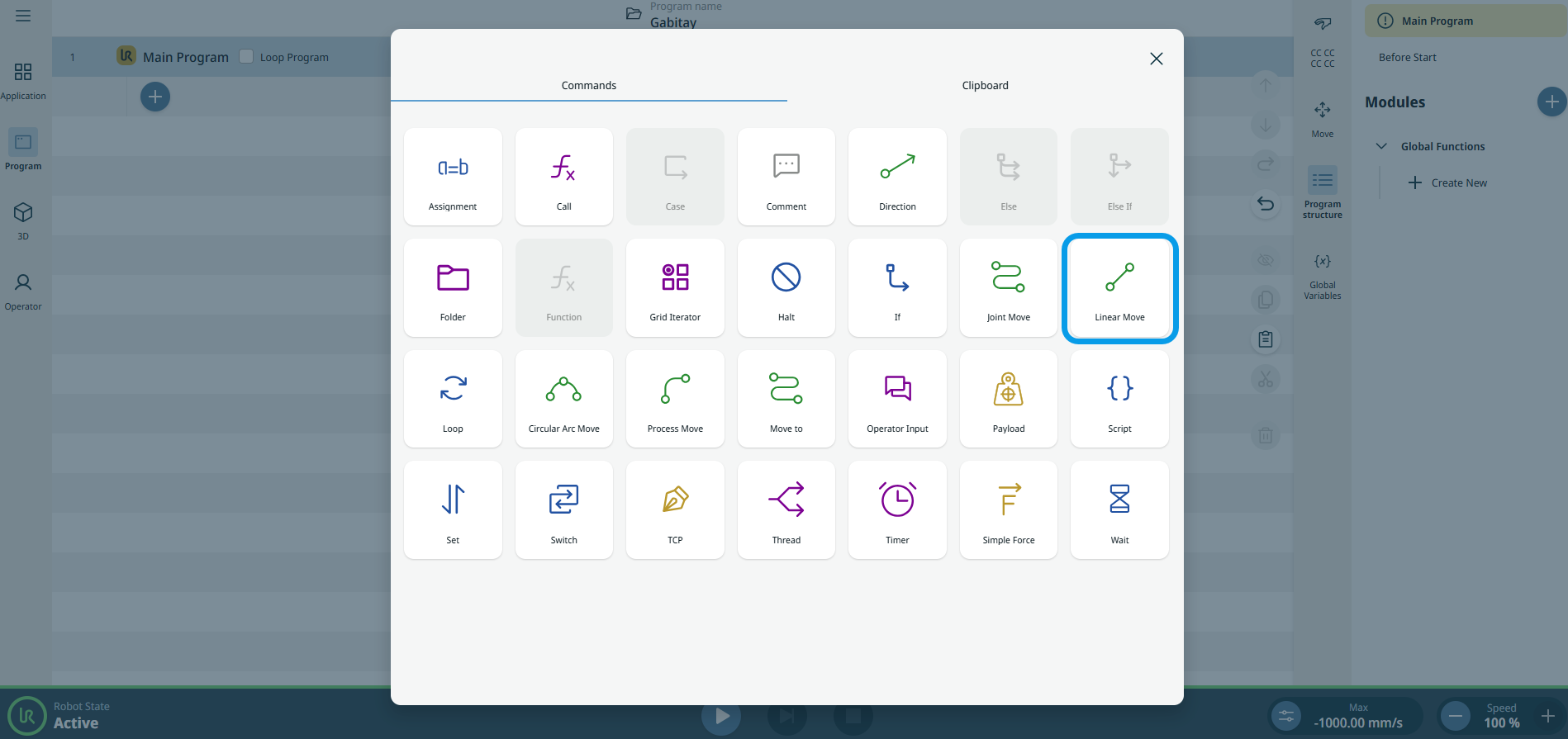
To access Linear Move command |
|
|
|
|
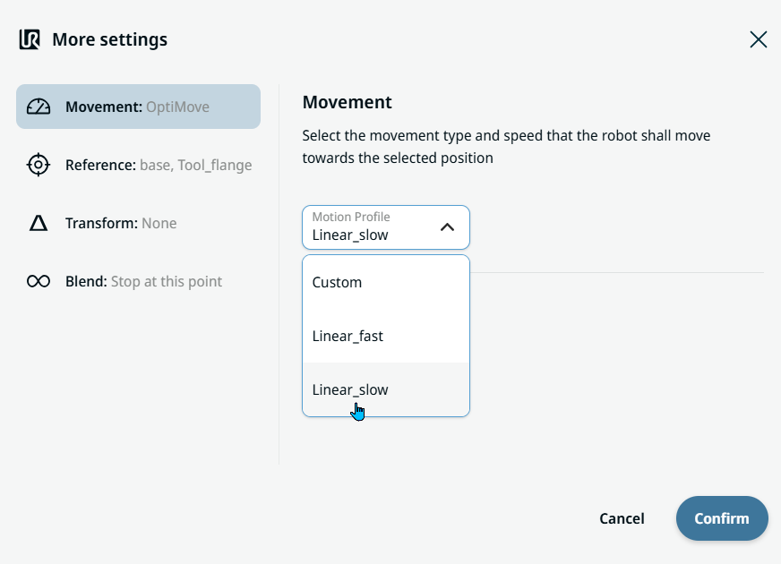
| Movement setting |
|
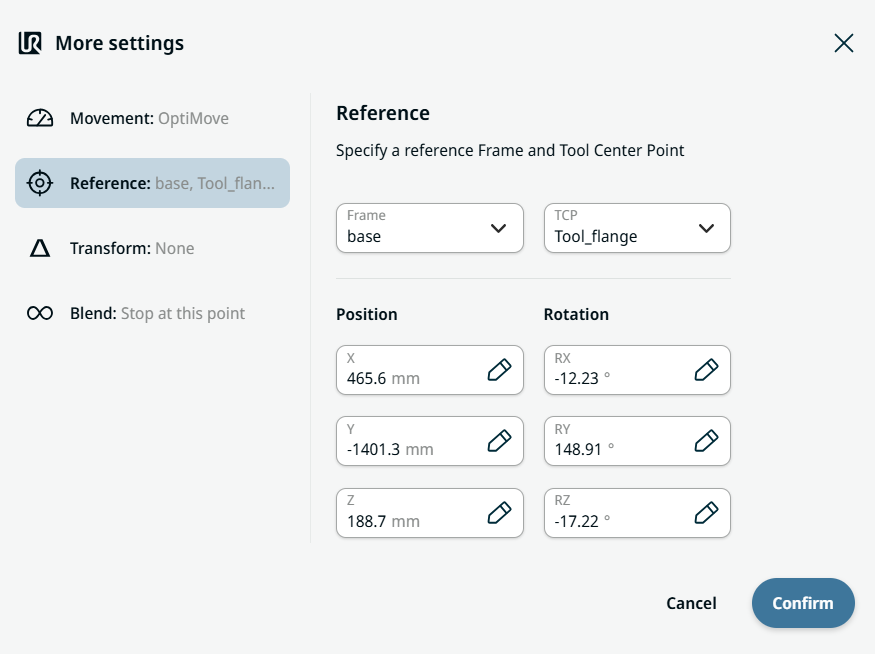
| Reference setting |
|
| Transform setting |
|
|
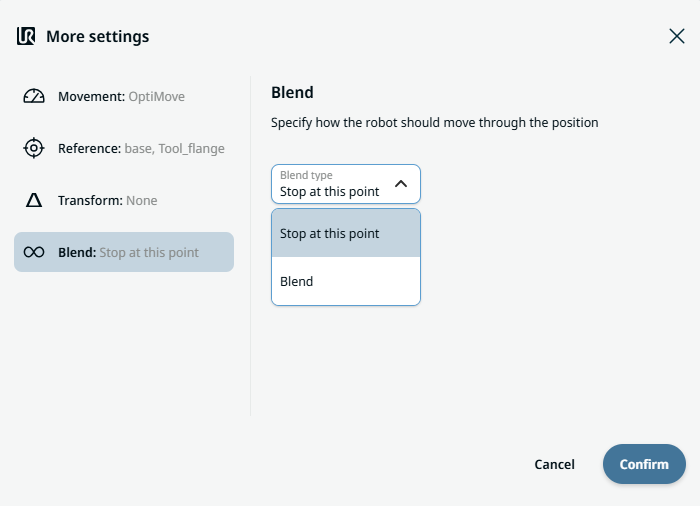
Blend setting |
|