Joint Move
| Beschreibung |
The Joint Move is a move command node that supports Motion Profiles. The command creates a movement from point A to point B that is optimal for the robot. Die Bewegung ist vielleicht keine direkte Linie zwischen A und B, ist allerdings optimal für die Start- und Endposition der Gelenke. Joint Move makes movements that are calculated in the robot arm joint space. Gelenke werden so gesteuert, dass deren Bewegungen zeitgleich enden. Diese Bewegungsart sorgt für eine gekrümmte Bahn, der das Werkzeug folgt.
|
|
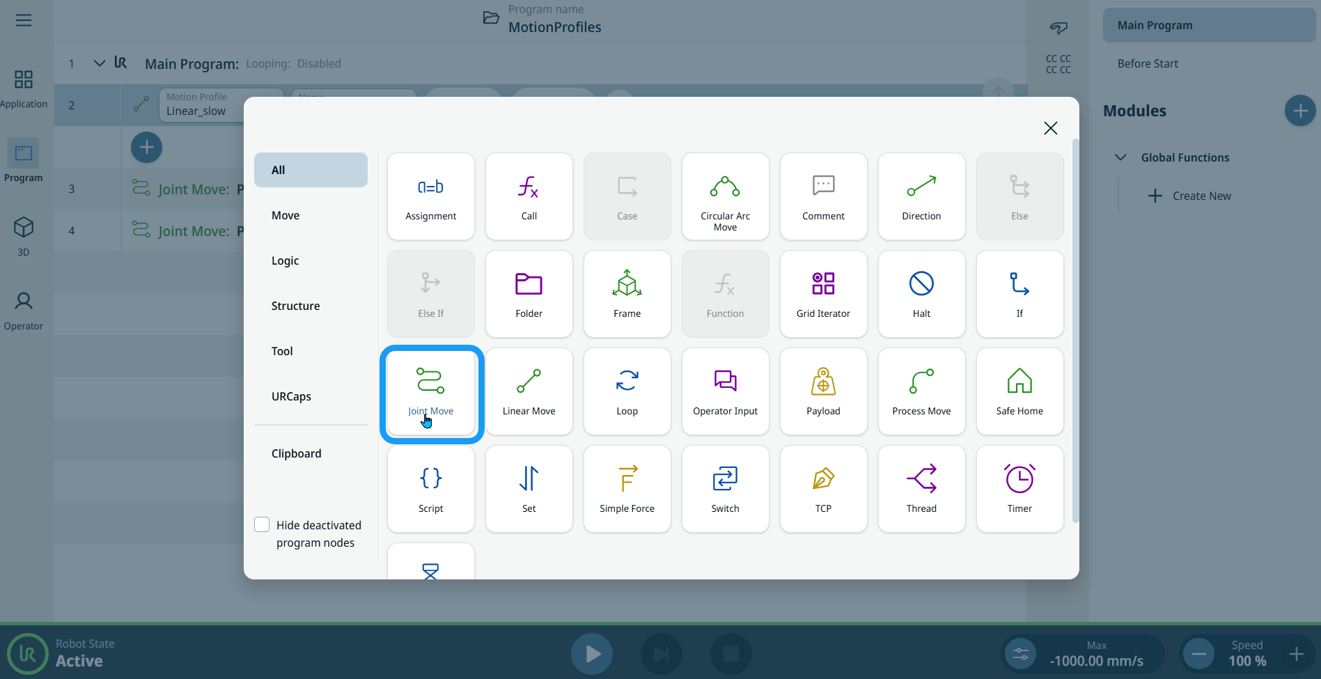
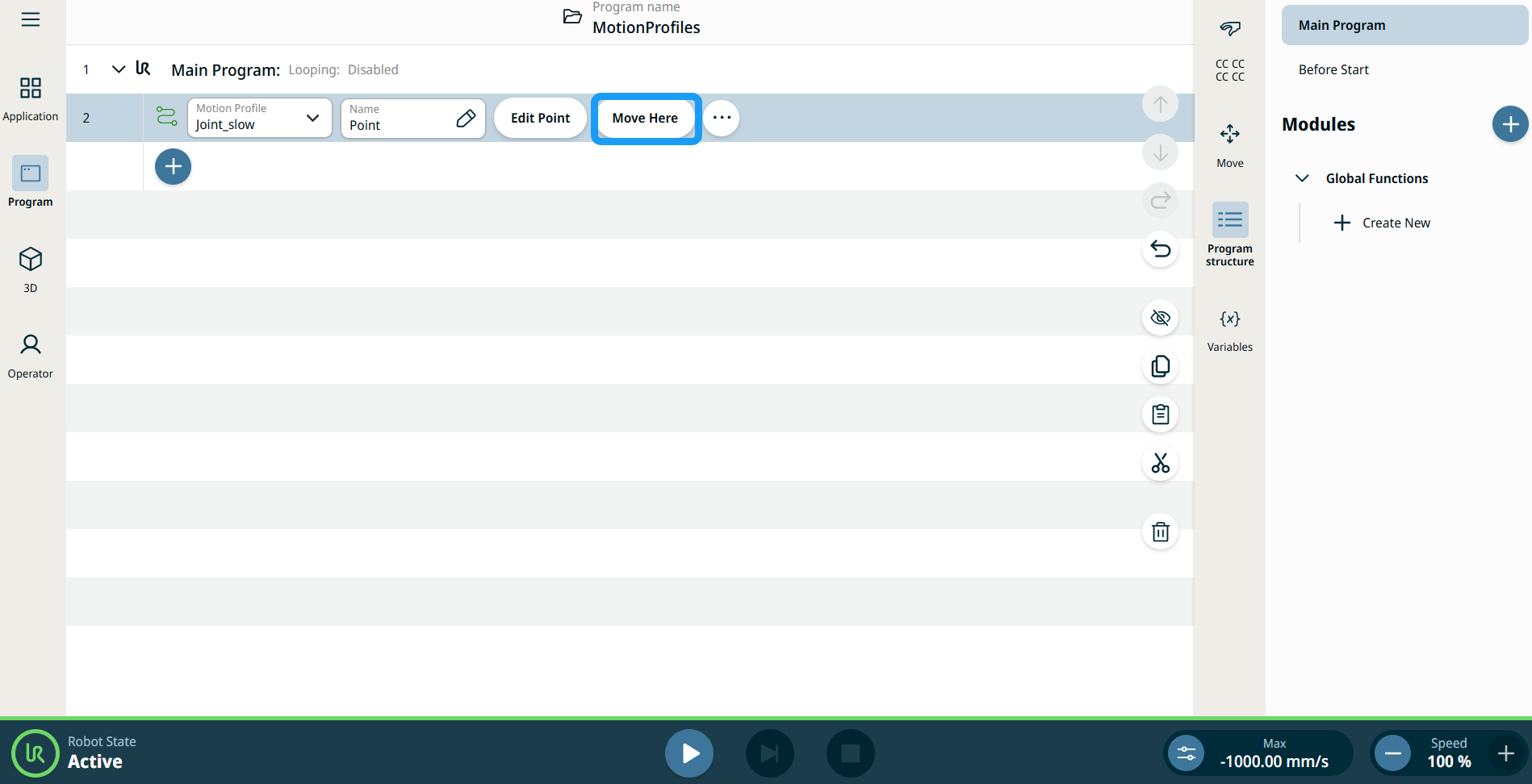
To access Joint Move command |
|
|
|
|
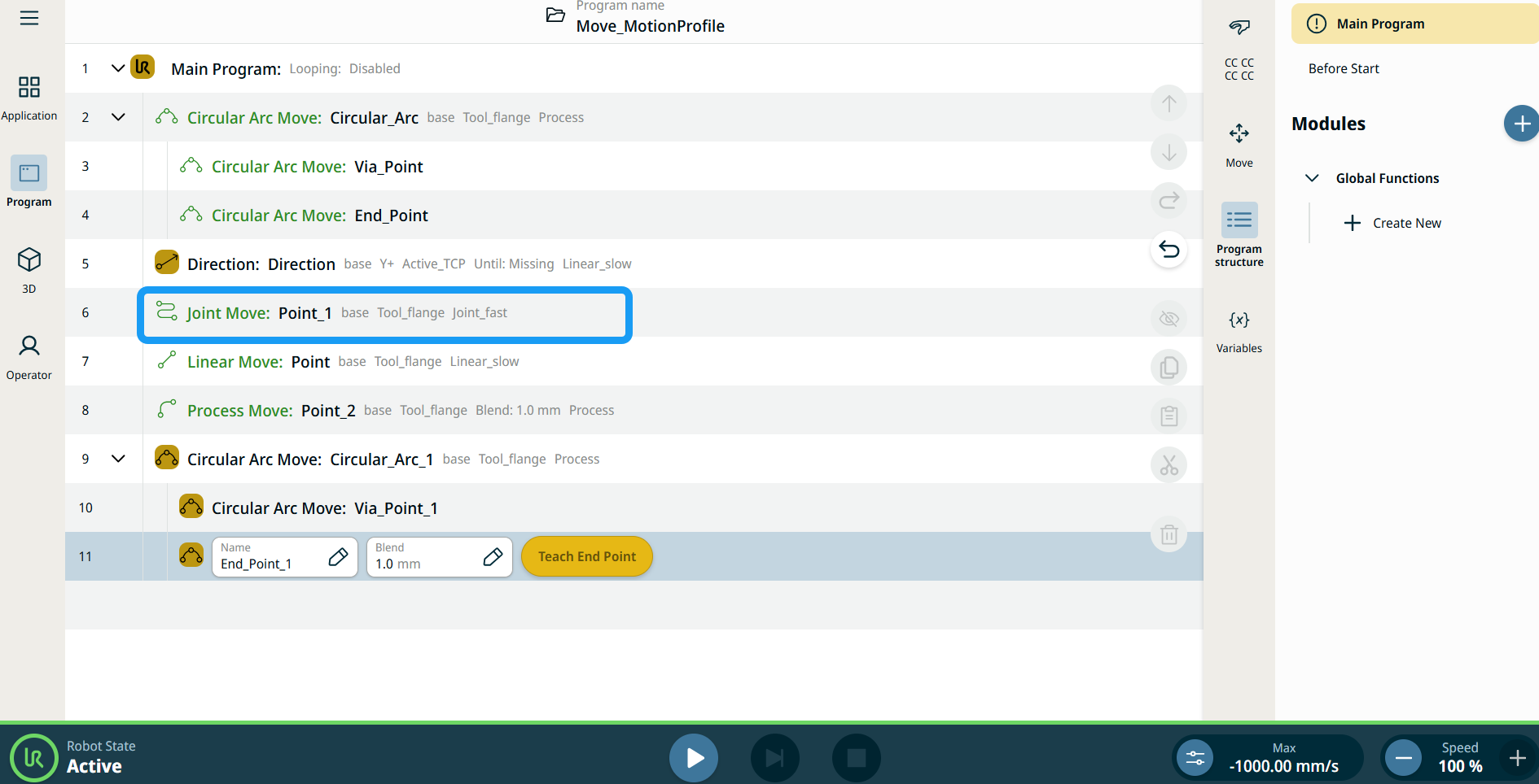
| Bewegungsprofil-Kennzeichnungen bei Bewegungsknoten |
Alle Bewegungsbezogenen Befehlsknoten in der Programmstruktur zeigen das Bewegungsprofil an, welches mit jedem Knoten verknüpft ist. Diese Funktion ermöglicht es Benutzern, das ausgewählte Bewegungsprofil bei einem Bewegen-Knoten zu sehen. Diese Funktion ist bei den folgenden Befehlsknoten implementiert: Bewegungsknoten mit benutzerdefiniertem Bewegungsprofil zeigen die Werte für die Geschwindigkeit und Beschleunigung an. |
|
|
|
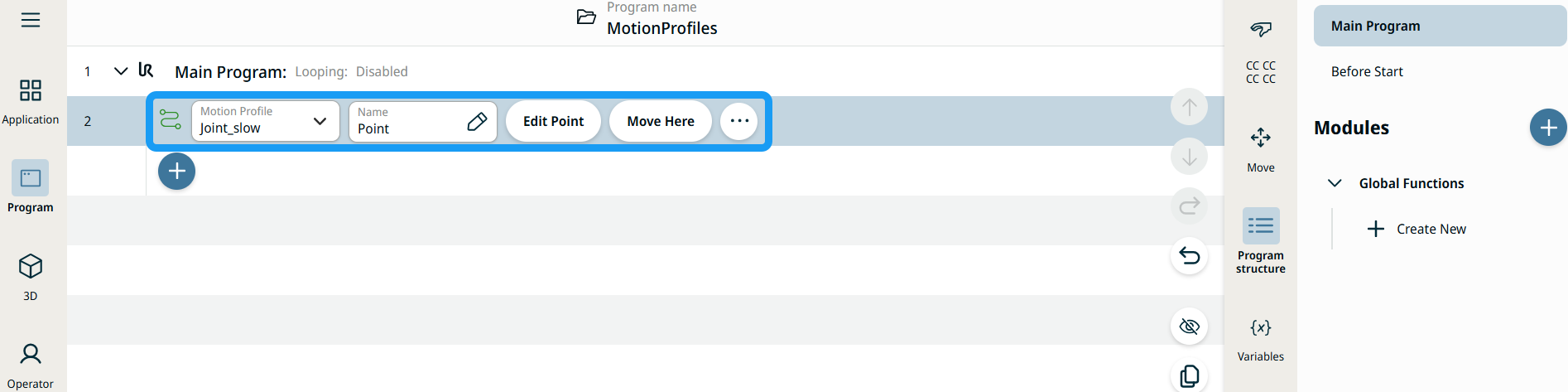
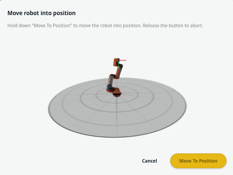
| Die Schaltfläche Hierher Bewegen verwenden |
Die Schaltfläche Hierher Bewegen ist bei den Befehlen Linear Move und Joint Move zu sehen. Mit dieser Funktion können Sie direkt aus der Programmstruktur zur Position eines Wegpunktes bewegen. Durch das Drücken auf die Schaltfläche Hierher Bewegen wird der Dialog Roboter in Position bewegen geöffnet. Die Schaltfläche ist sichtbar, wenn der Wegpunkt geteacht wurde und ist nur aktiv, wenn der Roboter sich im Normalen oder im Reduzierten Modus befindet.
|
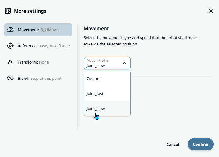
| Movement setting |
|
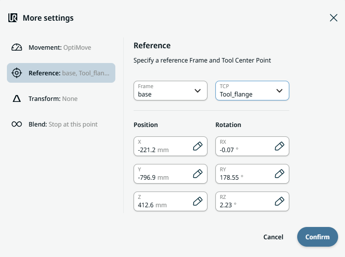
| Reference setting |
|
| Transform setting |
|
|
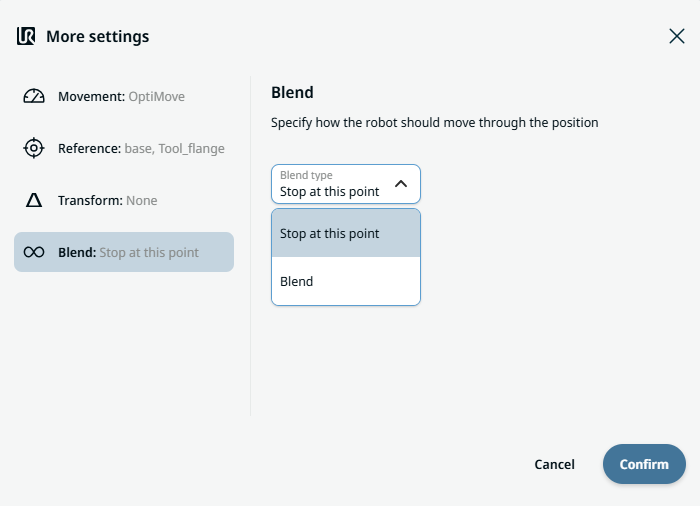
Blend setting |
|