Dismantling the Control Box

Warnings
Before replacing ANY components inside the Control Box, you MUST do a complete shutdown.
Follow the first 3 steps in section Complete Rebooting Sequence
Exercise caution when handling ESD sensitive parts.
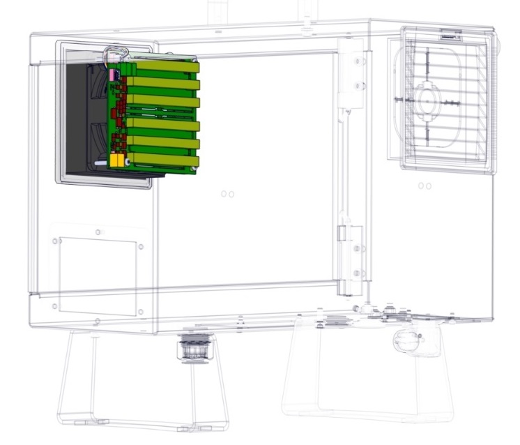
See section 2.
If possible, lay the Control Box on its back.
Assembling is done in revers from the steps shown.
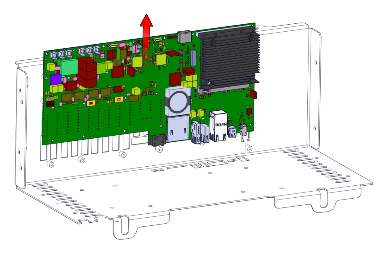
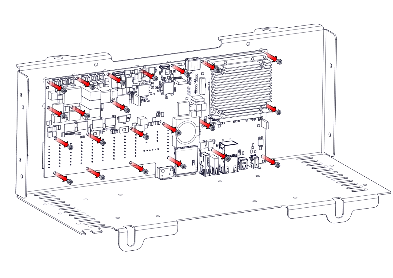
Dismantling steps
  1. Power off Control Box – follow step 1 to 3 in section Complete Rebooting Sequence
  2. Remove all the I/O Terminals, the Fuse, SD-card and any other I/O etc. that may be connected.
  3. Remove the Teach Pendant, see Section Replacing the Teach Pendant: Standard TP
  4. Lay the Control Box on the backside and remove the four nuts.
  5. Take out the Control Box bracket and place it on the edge of the Control Box as shown below.
 
  1. Remove the wires connecting the Control Box bracket and the Control Box.
    Take note of the connections or consult the eletrical diagram in Section 7. Electrical drawings

Power Supply

UR5e, UR10e and UR16e

UR3e

 
  1. Remove the four screws on the bottom of the power supply, then remove the power supply.A close up of a map

Description generated with high confidence
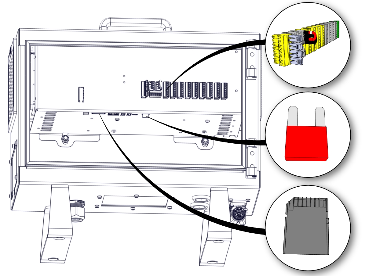
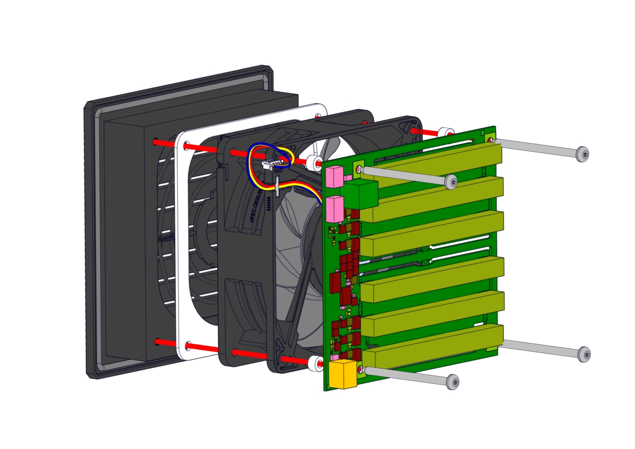
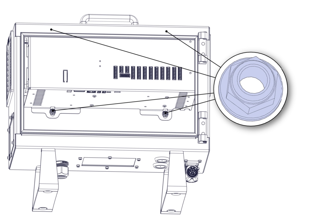
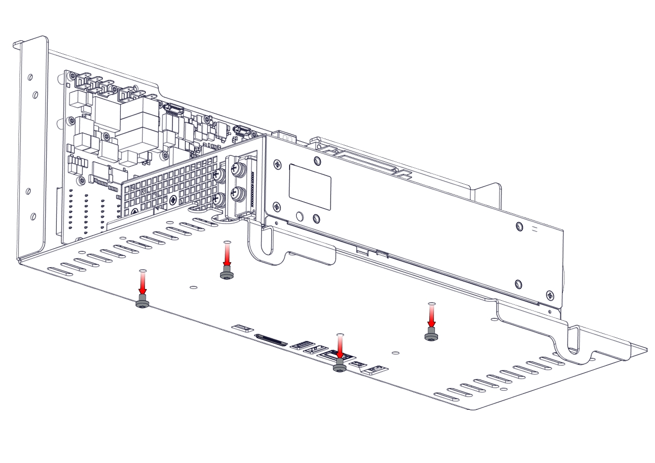
When assembling, the screws must not be tightened with a torque greater than 1.0 Nm
  1. Remove the twenty-two screws and remove the Control Board upward. A close up of a map

Description generated with high confidence
 

  1. Removing the Energy Eater and fan assembly. Remove the four screws.
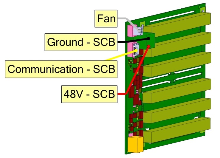
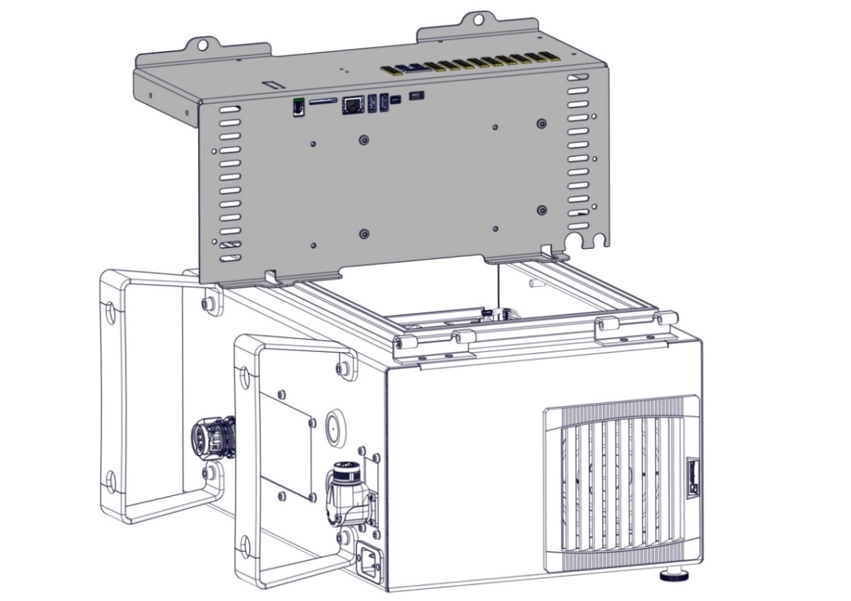
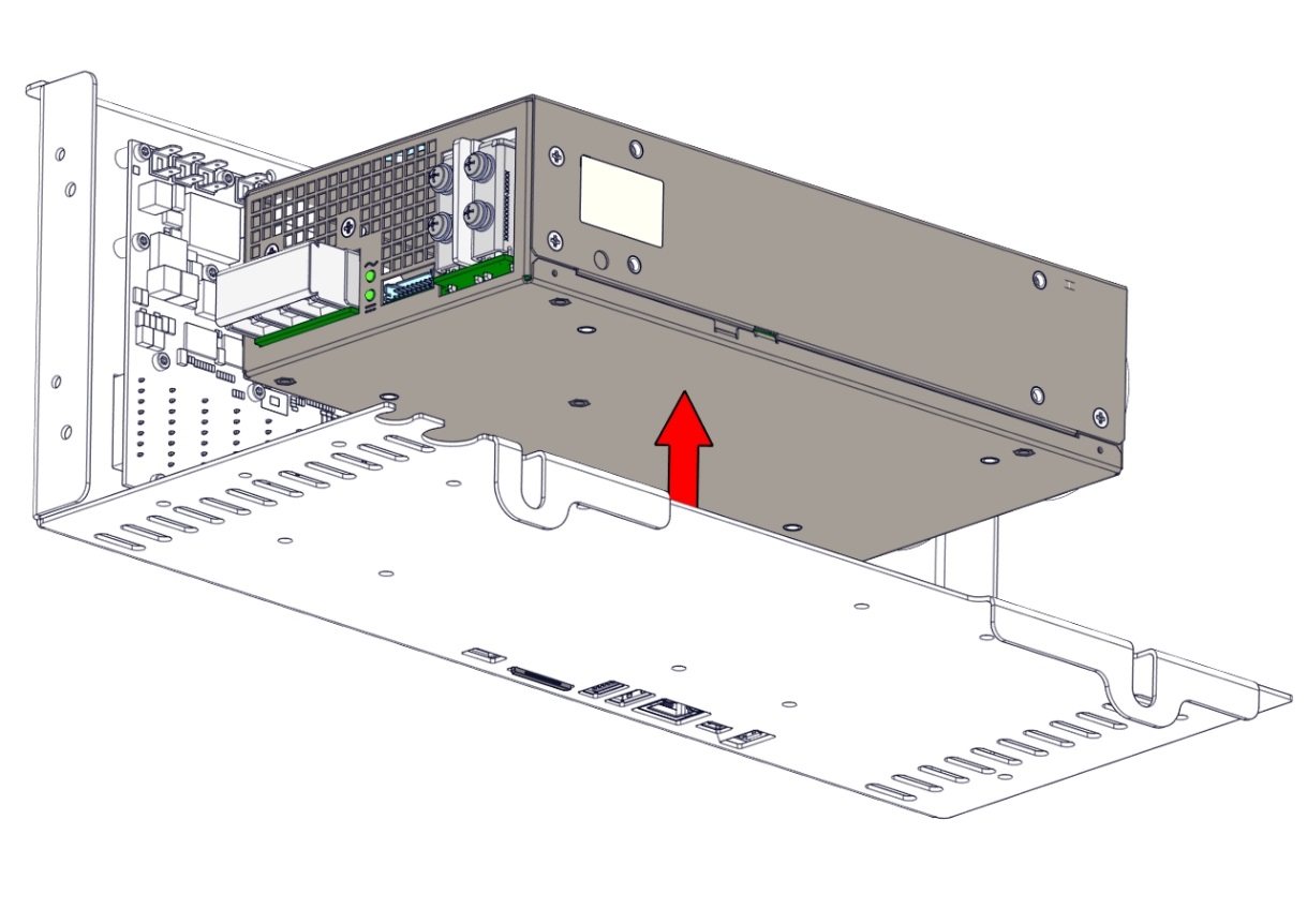
When assembling, remember to place the round spacers behind the Energy Eater board.