Dismantling the Control Box
Follow the first 3 steps in section Complete Rebooting Sequence
See section 2. Handling ESD-Sensitive Parts
If possible, lay the Control Box on its back.
Assembling is done in revers from the steps shown.
- Power off Control Box – follow step 1 to 3 in section Complete Rebooting Sequence
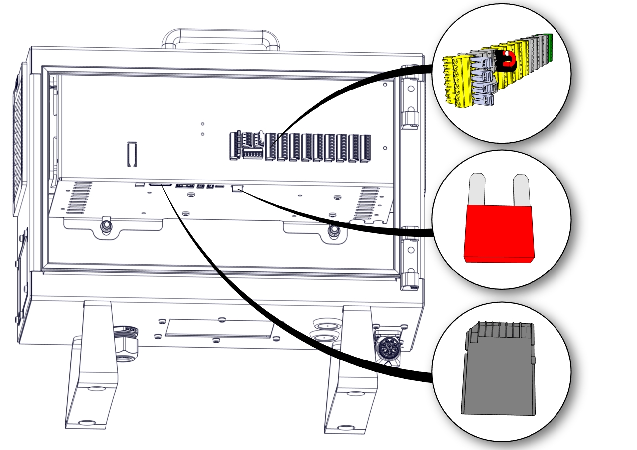
- Remove all the I/O Terminals, the Fuse, SD-card and any other I/O etc. that may be connected.
- Remove the Teach Pendant, see Section Replacing the Teach Pendant: Standard TP
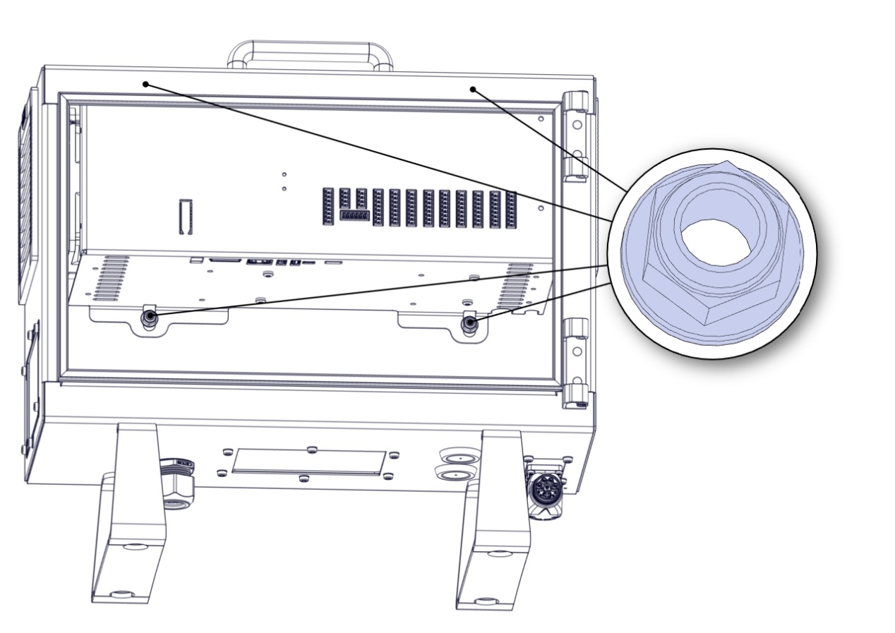
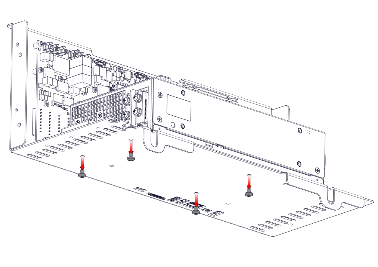
- Lay the Control Box on the backside and remove the four nuts.
- Take out the Control Box bracket and place it on the edge of the Control Box as shown below.
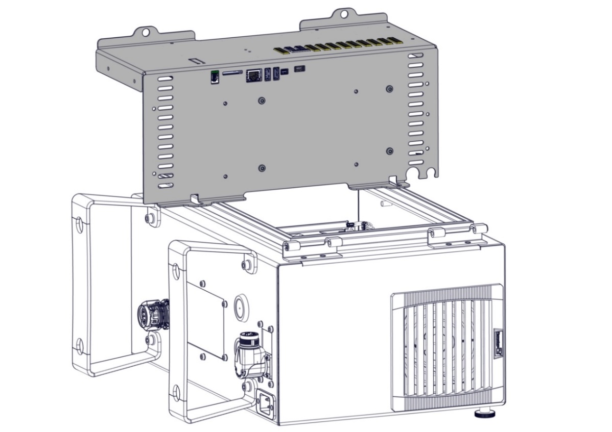
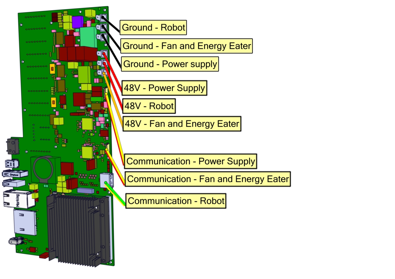
- Remove the wires connecting the Control Box bracket and the Control Box.
Take note of the connections or consult the eletrical diagram in Section 7. Electrical drawings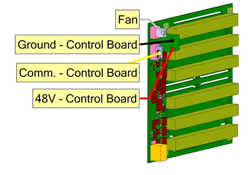
|
Power Supply |
||
|
|
||
|
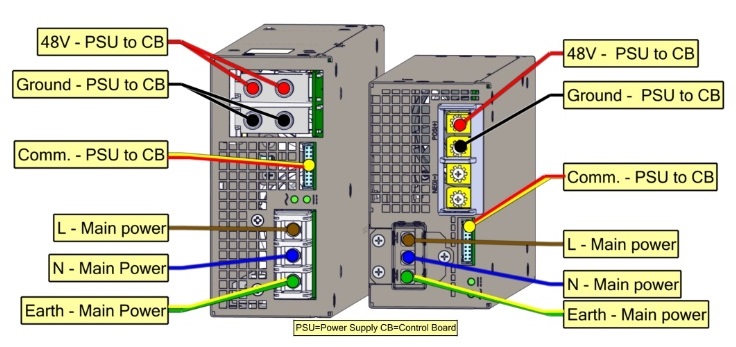
- Remove the four screws on the bottom of the power supply, then remove the power supply.

 Nm
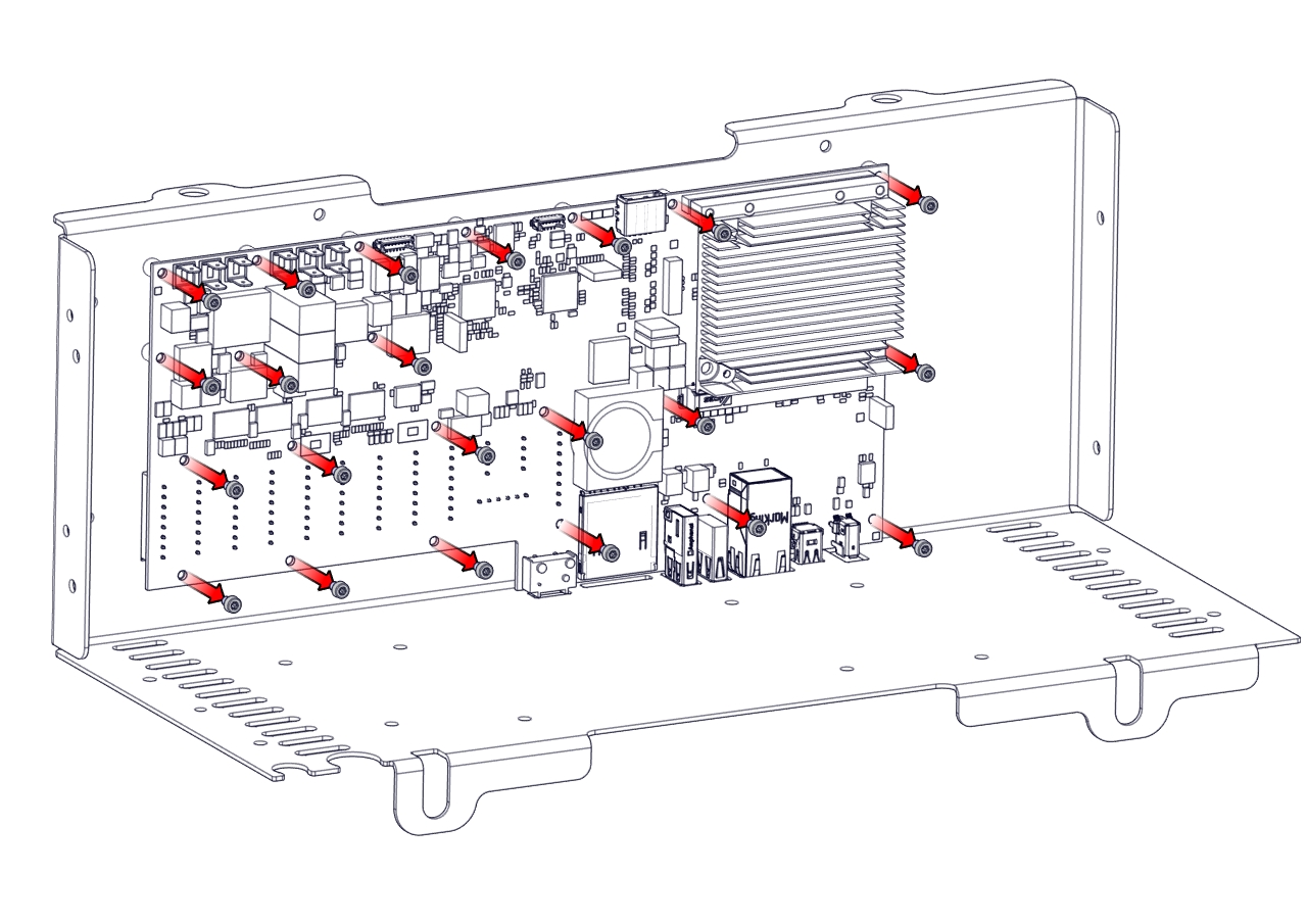
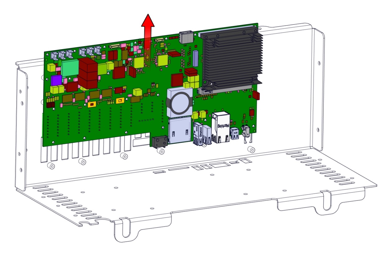
Nm - Remove the twenty-two screws and remove the Control Board upward.
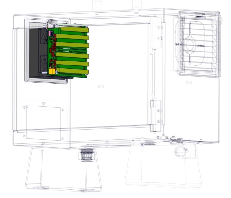
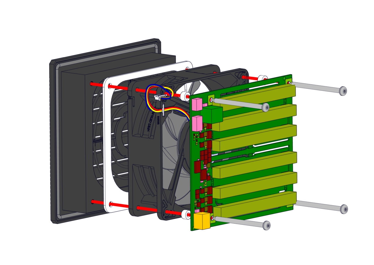
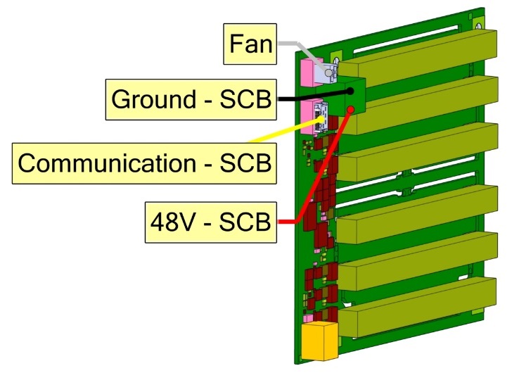
- Removing the Energy Eater and fan assembly. Remove the four screws.
|
|
|
|
|
|