URCaps
| Description |
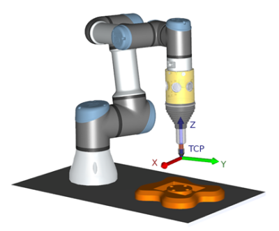
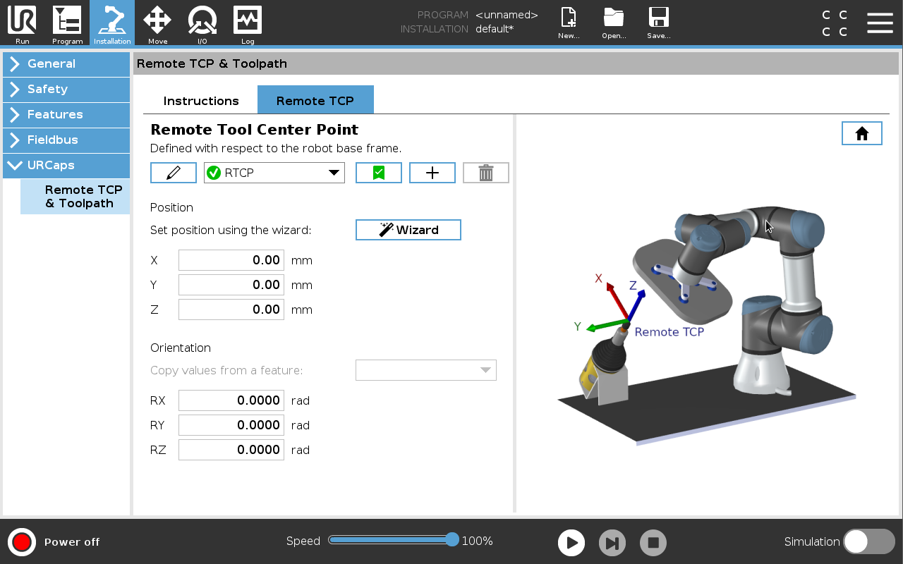
The Remote TCP and Toolpath URCap allows you to set Remote Tool Center Points (RTCP), where the tool center point is fixed in space, relative to the base of the robot. The Remote TCP and Toolpath URCap also allows for programming waypoints and circle moves, and generating robot motion based on imported toolpath files defined in third-party CAD/CAM software packages.
Similar to a regular TCP (see ) you can define and name an RTCP in the Installation Tab’s Setup. You can also complete the following actions:
|

| Setting the Remote TCP from a Feature |
Set an RTCP using a Feature to allow the robot to be jogged relative to the RTCP while creating RTCP Waypoints and RTCP Circle Moves.
|
| Remote TCP Movement Types | |
| RTCP_MoveP |
Similar to a regular MoveP, the RTCP_MoveP defines the tool speed and acceleration the Robot Arm moves relative to the Remote TCP. See . |
| RTCP Circle move |
Similar to a regular Circle move, the RTCP Circle move can be added to an RTCP_MoveP to make circular movements. See . The maximum speed of a Circle Move may be lower than the specified value. The circle radius is r, the maximum acceleration is A, and the maximum speed cannot exceed Ar due to centripetal acceleration.
|
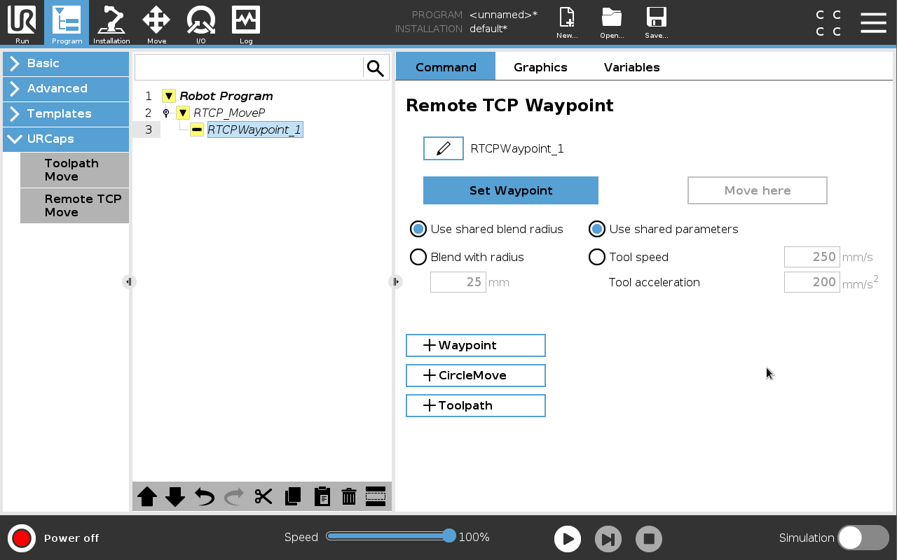
| Remote TCP Waypoint |
Similar to regular waypoints, RTCP Waypoints allow a tool to move linearly using constant speed and circular blends. The default blend radius size is a shared value between all the waypoints. A smaller blend radius size sharpens the path turn. A larger blend radius size smoothens the path. RTCP Waypoints are taught by physically moving the Robot Arm to a desired position.
|
| Teaching Remote TCP Waypoints |
|
| Configuring an RTCP Waypoint |
Use blends to enable the robot to smoothly transition between two trajectories. Tap Use Shared Blend Radius or tap Blend with radius to set the blend radius for a waypoint from an RTCP_MoveP. A physical time node (e.g. Move, Wait) cannot be used as a child of an RTCP_MoveP node. If an unsupported node is added as a child to an RTCP_MoveP node, the program fails to validate.
|
| Remote TCP |
Configuring a Remote TCP for Toolpath Moves
|
| Remote TCP PCS |
The Remote TCP Part Coordinate System (PCS) is defined as fixed relative to the robot tool flange. Tap the wand, on the PolyScope screen, to activate the wizard to teach the Remote TCP PCS. You can use either of the teaching methods described below.
|
| Configuring a Remote TCP PCS |
Use this method if the PCS can be set on the part surface.
Otherwise, use this method.
|

| Setting a Variable PCS |
For advanced use cases, where the part is not grasped with high consistency, you can set a Variable PCS to adjust the toolpath moves according to the part location and orientation relative to the robot tool flange. You can create a pose variable tied to an external sensor that can detect the PCS location and orientation.
|
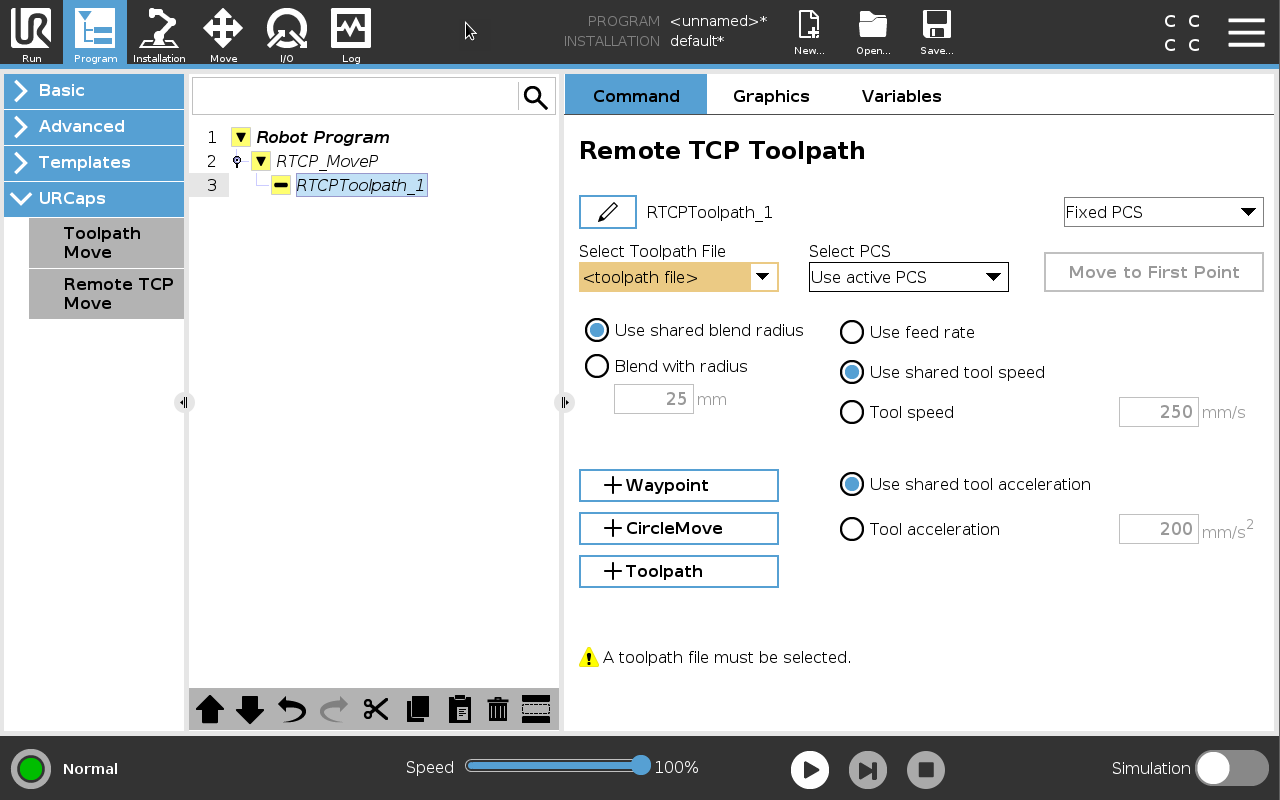
| Configuring a Remote TCP Toolpath Node |
The following section explains how to use a variable PCS in a Remote TCP Toolpath node.
You can ensure the robot motion is identical, each time the toolpath is executed, by adding a MoveJ with a Use Joint Angles set to move to a fixed joint configuration before executing the toolpath. See Move
|

| Regular TCP Toolpath Moves |
Similar to configuring a Remote TCP Toolpath Move, a regular TCP Toolpath Move requires the following:
|
| Configuring and Importing a Toolpath File |
This is similar to configuring a Toolpath (see Configuring a Toolpath using CAD/CAM Software) and importing Toolpath (see Importing a G-code Toolpath into PolyScope). |
| Configuring a Regular TCP |
|
| Configuring a Plane Feature PCS |
|
| Configuring a Toolpath Node |
You can ensure the robot motion is identical, each time the toolpath is executed, by adding a MoveJ with a Use Joint Angles set to move to a fixed joint configuration before executing the toolpath. See Move
|