Direction

Description

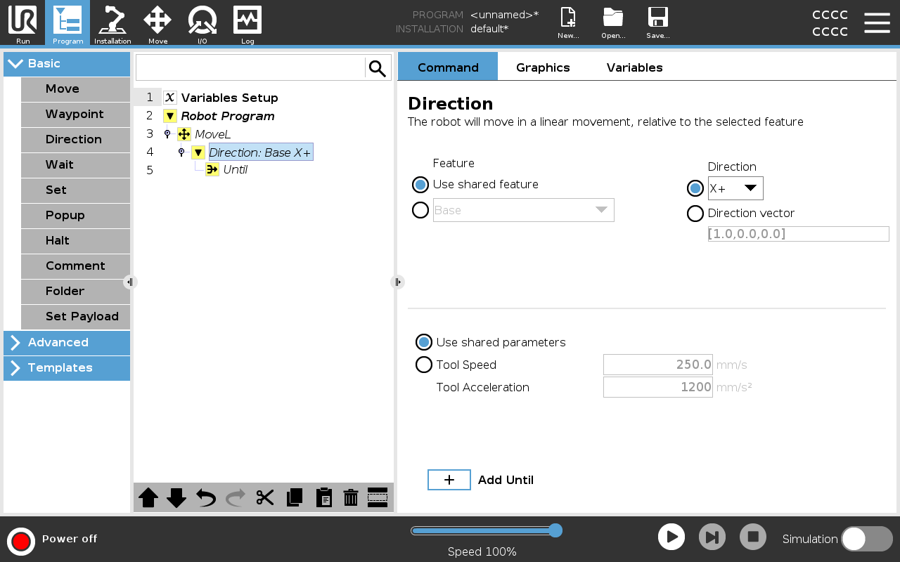
The Direction command specifies a motion relative to feature axes or TCPs.

The robot moves in the path specified by the Direction program node until that movement is stopped by an Add Until condition.


Direction

The Direction command allows you to make the robot move in a specific direction.

Example

Direction vectors of [100,0,0] and [1,0,0] have the same effect on the robot; use the Speed Slider to moving along the x-axis at a desired speed. The values of the numbers in the direction vector only matter relative to each other.

Add a Direction movement to a robot program
  1. In your robot program, select the place or node where you wish to add a Direction command.

  2. Under Basic, tap Direction to add a linear movement to your Program Tree.

  3. In the Direction field, under Feature, define the linear movement.

    1. Select if you use the shared feature
      or the Base/Tool

    2. Select the cartesian direction from the Direction drop-down
      or write the Direction vector manually

    3. Select Shared parameters or define the tool speed and acceleration.

  1. Click Add Until to add a method of stopping the directional movement.

Select the feature and direction

Difference between Shared Feature or BASE/TOOL


Difference between Direction and writing the Direction Vector


The Direction Vectors define a custom code expression that is resolved to a unit vector.


Direction Movement

There are different ways to stop direction movement.


In the Direction field, tap the Add Until button to define and add stop criteria to your Program Tree.

Direction Vector

The Direction Vector settings allow you to define the vector direction for linear motion. Use the Tool Speed and Tool Acceleration for the following:

  • to define linear motion relative to multiple feature axes

  • to calculate the direction as a mathematical expression