Dismantling the Control Box
Failure to completely shut down the Control Box before replacing any components can lead to serious injury due to electrical hazards.
-
Before replacing ANY components inside the Control Box, you MUST do a complete shutdown.
-
Follow the first 3 steps in section Complete Rebooting Sequence
Failure to exercise caution when handling ESD sensitive parts can increase the risk of injury. See section 2. Handling ESD-Sensitive Parts
-
Exercise caution when handling ESD sensitive parts
-
If possible, lay the Control Box on its back while working on it.
To Dismantle the Control Box:
The illustrations below can differ from actual hardware design.
- Power off Control Box – follow step 1 to 3 in section Complete Rebooting Sequence
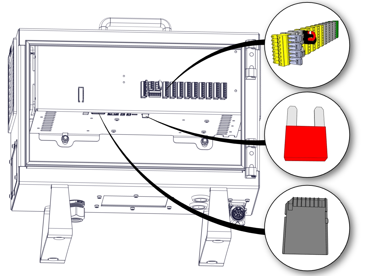
- Remove all the I/O Terminals, the Fuse, SD-card and any other I/O etc. that may be connected.
- Remove the Teach Pendant, see Section Replacing the Teach Pendant: Standard TP
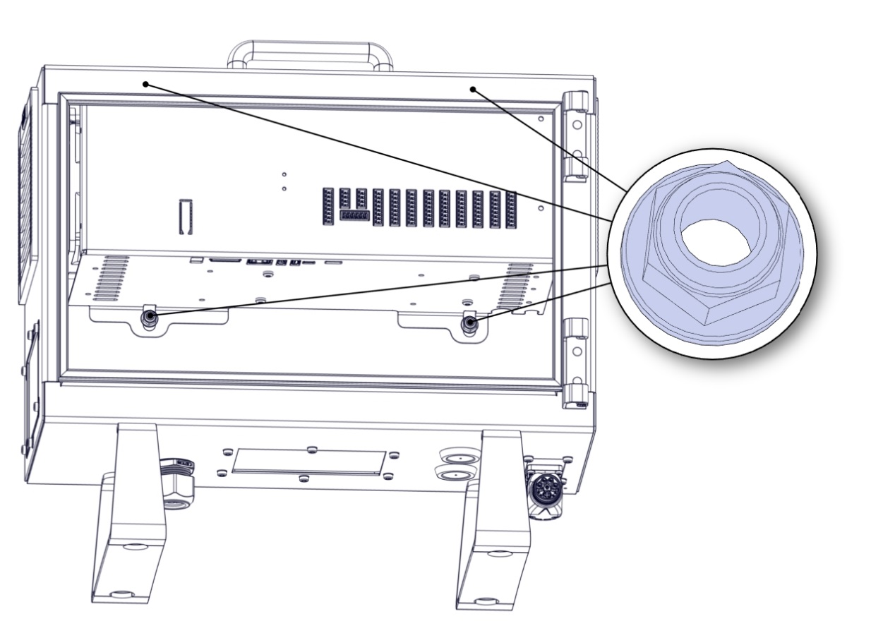
- Lay the Control Box on the backside and remove the four nuts.
- Take out the Control Box bracket and place it on the edge of the Control Box as shown below.
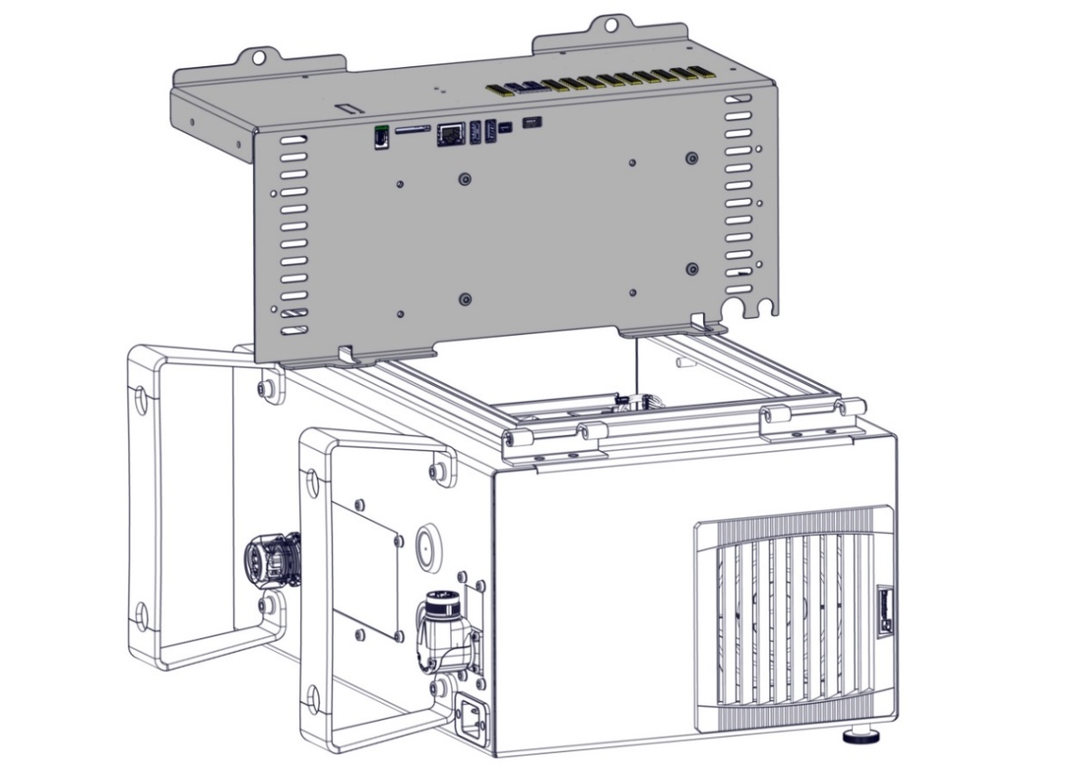
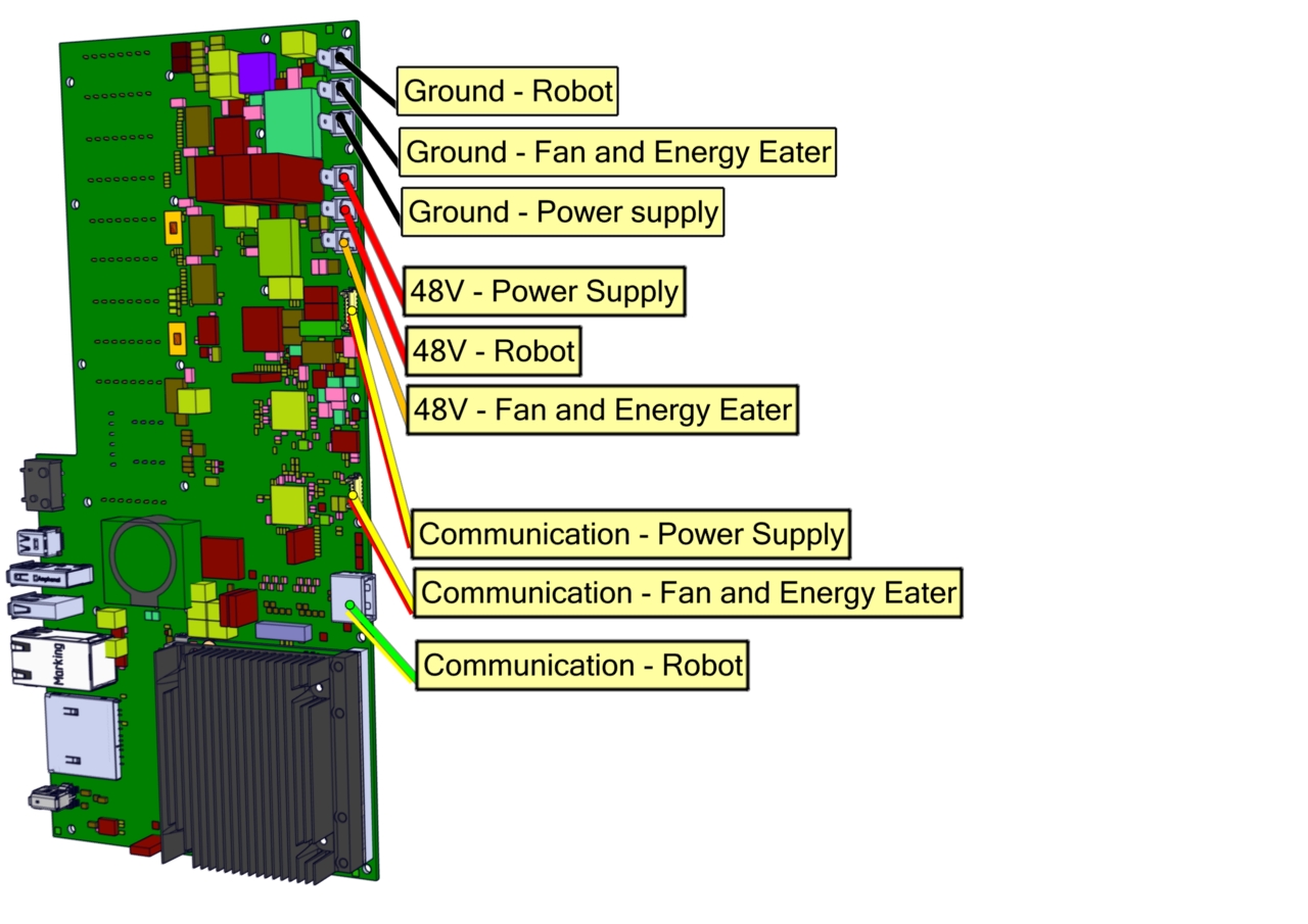
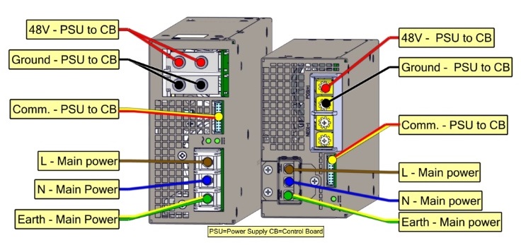
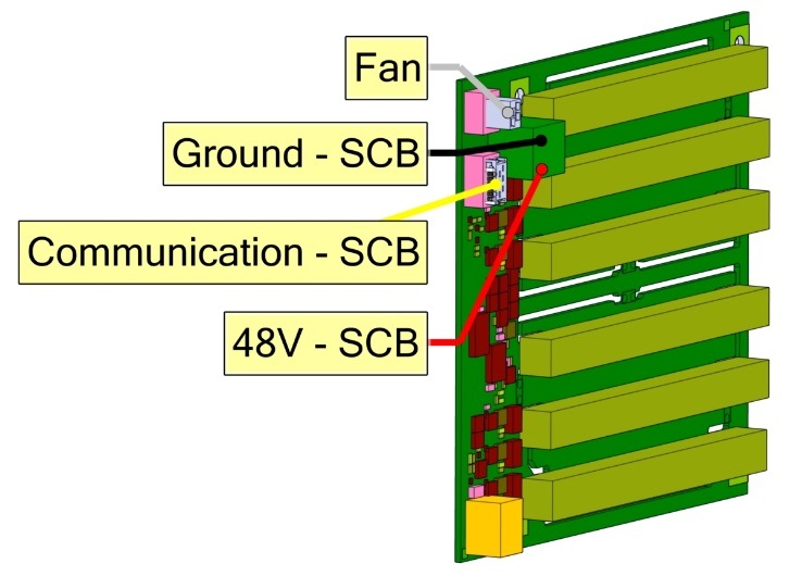
- Remove the wires connecting the Control Box bracket and the Control Box.
Take note of the connections or consult the eletrical diagram in Section 7. Electrical drawings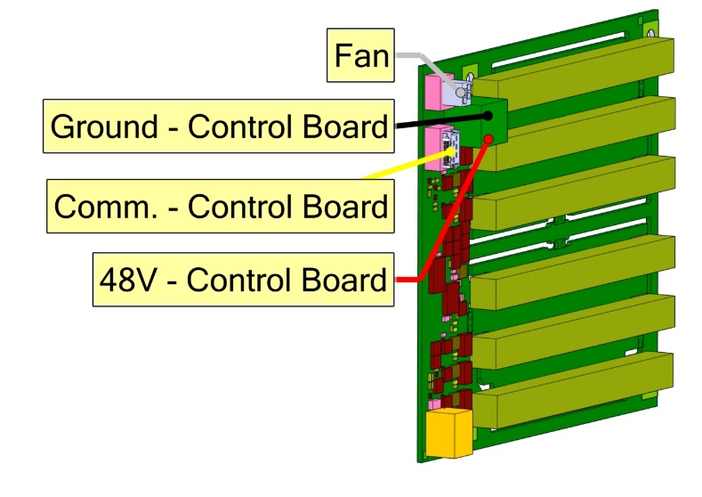
|
Power Supply |
||
|
|
||
|
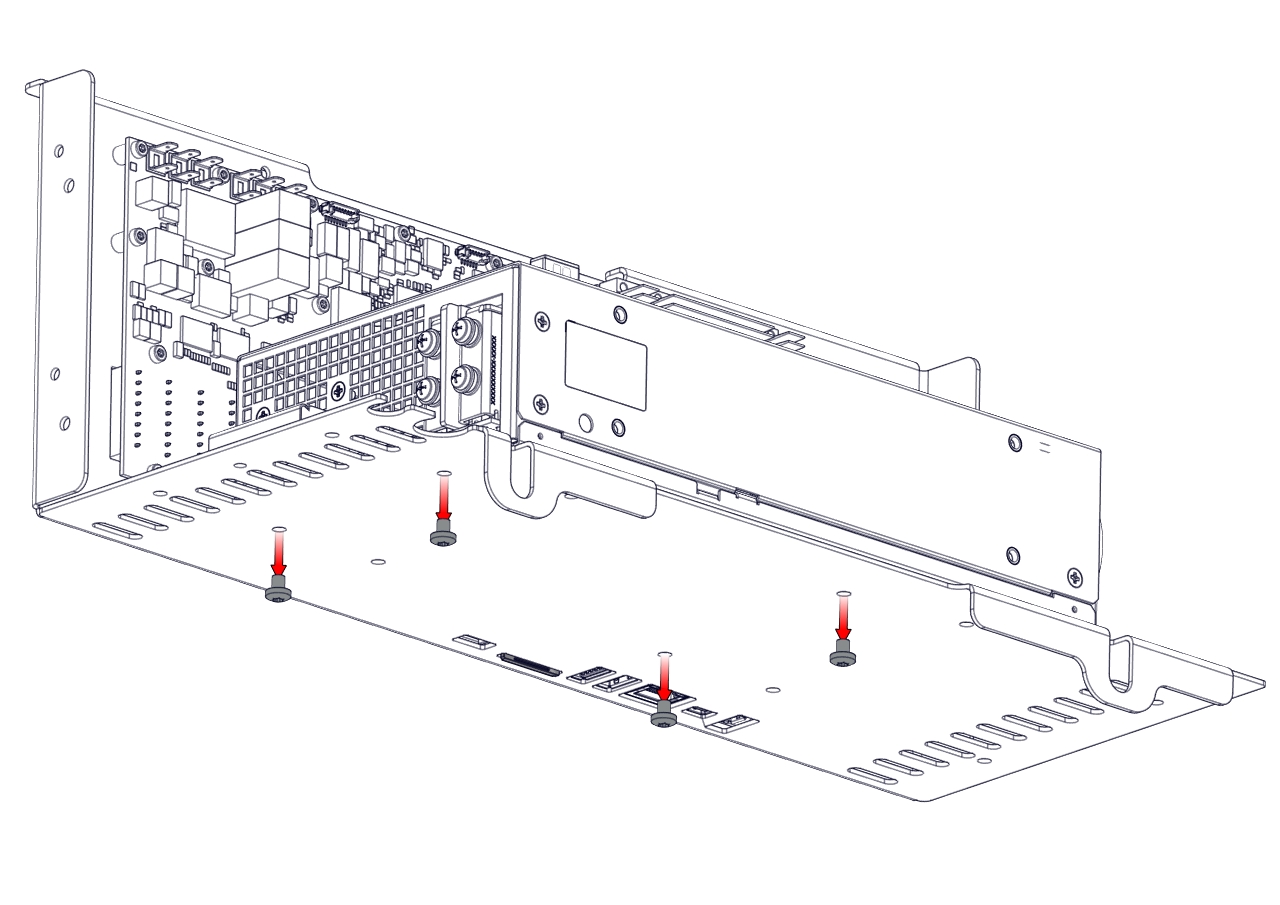
- Remove the four screws on the bottom of the power supply, then remove the power supply.

 Nm
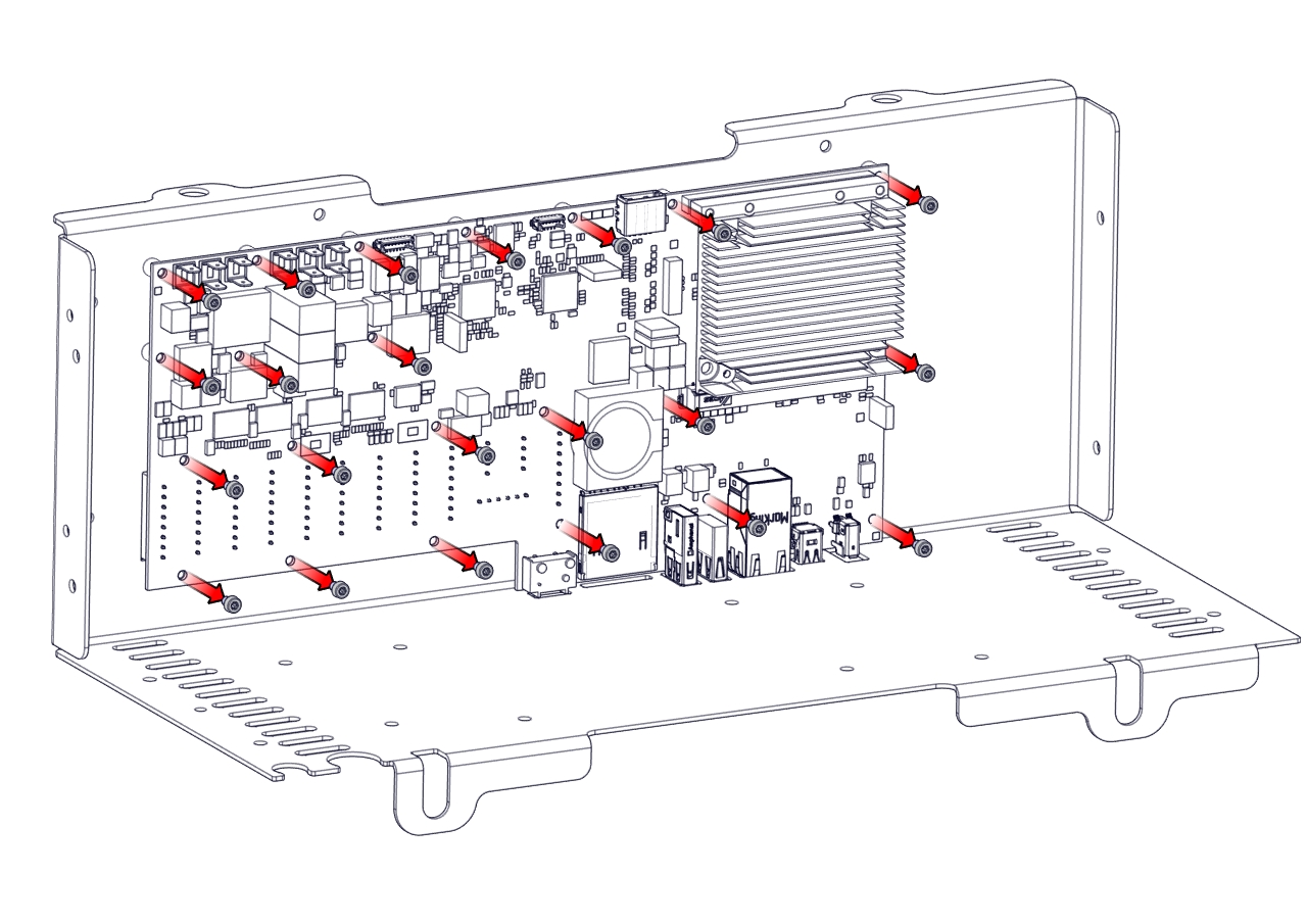
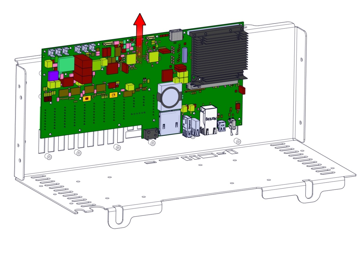
Nm- Remove the twenty-two screws and remove the Control Board upward.
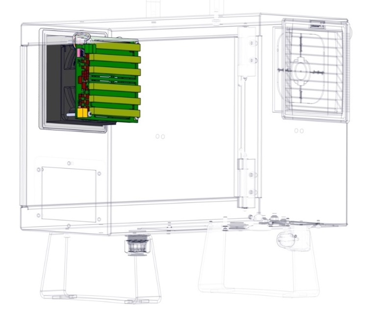
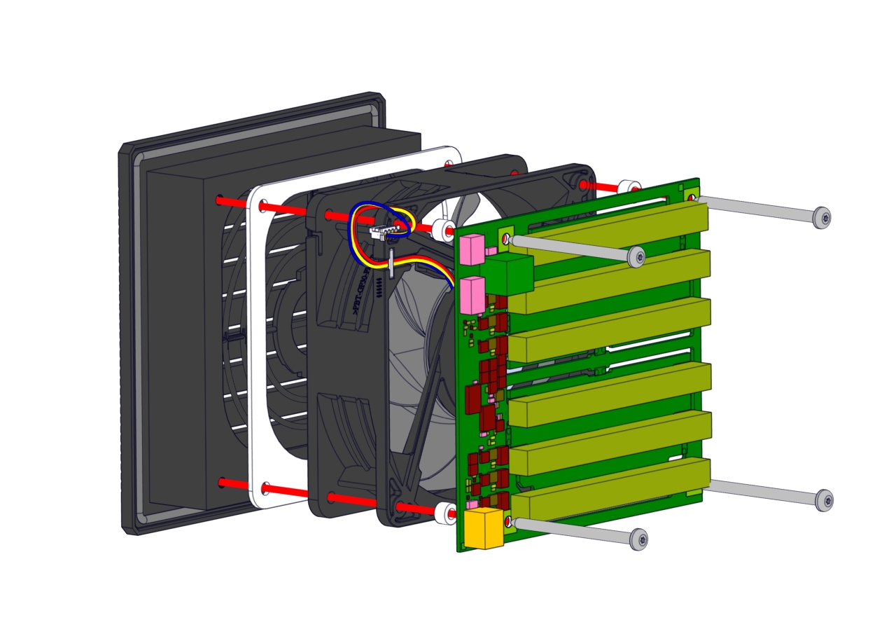
- Removing the Energy Eater and fan assembly. Remove the four screws.
-
Re-assembling the Control Box is done in reverse of the steps shown above.