First Boot
| Description |
The first boot is the initial sequence of actions you can take to configure the robot for the first time after assembly. This initial sequence requires you to:
|
|
Failure to verify the payload and installation before starting up the robot arm can lead to injury to personnel and/or property damage.
Incorrect payload and installation settings prevent the robot arm and Control Box functioning correctly.
Starting up the robot in lower temperatures can result in lower performance, or stops, due to temperature dependent oil and grease viscosity.
|
Powering On the Robot
| To power on the robot |
Powering on the robot turns on the Control Box and loads the display on the TP screen.
|
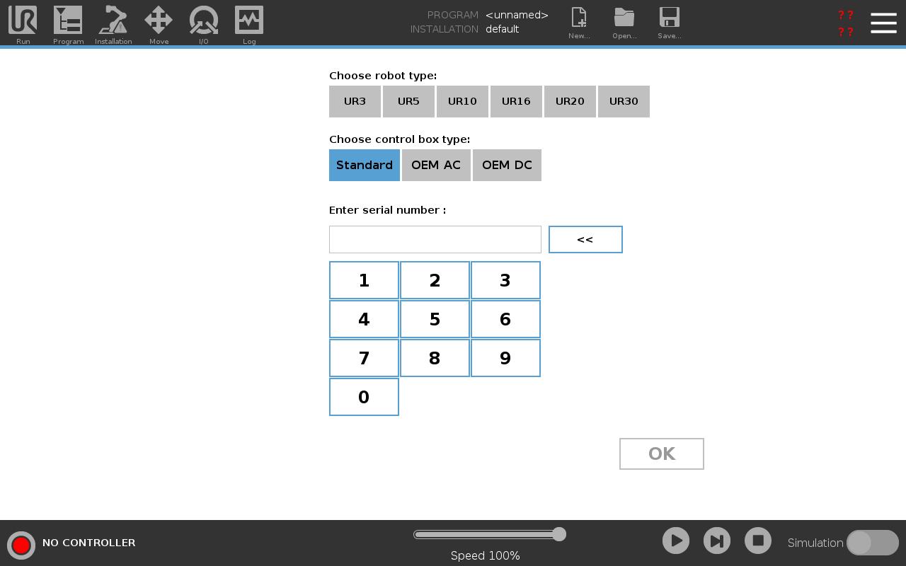
Inserting the Serial Number
| To insert the serial number |
Installing your robot for the first time requires you to enter the serial number on the robot arm. This procedure is also required when you re-install the software, for example when you install a software update. |
|
|
It can take a few minutes for the start screen to load.
|
Confirming the Safety Configuration
| To confirm the safety configuration |
On your first start up, you need to confirm the robot's safety configuration.
|
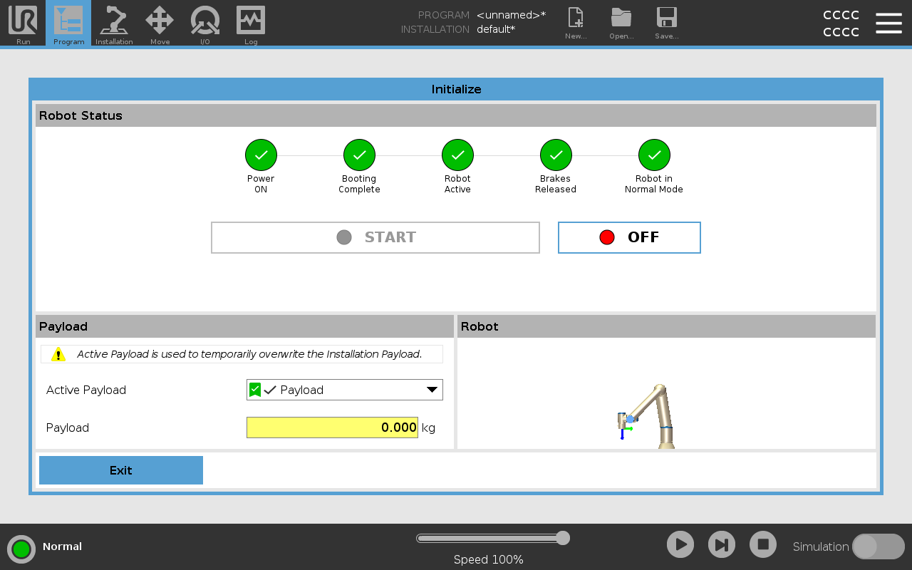
Starting the Robot Arm
| To start the robot |
Starting the robot arm disengages the braking system, allowing you to start moving the robot arm and to start using PolyScope. You can follow the progression as the circles in the Initialize box change color. The Initialize button in the Footer also changes color depending on the status of the robot arm.
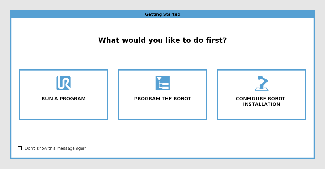
If the robot arm mounting is verifed, you can tap START to continue releasing all the joint brakes, preparing the robot arm for operation. The Getting Started screen can be displayed, prompting you to begin programming the robot. |
Verifying the Robot Arm Mount
| To verify the mounting |
During the first start up, you may need to verify how the robot arm is mounted. If the robot arm is mounted on a flat table or floor, no change is needed. If the mounting of the robot arm is not verified, the Getting Started dialog box appears.
|
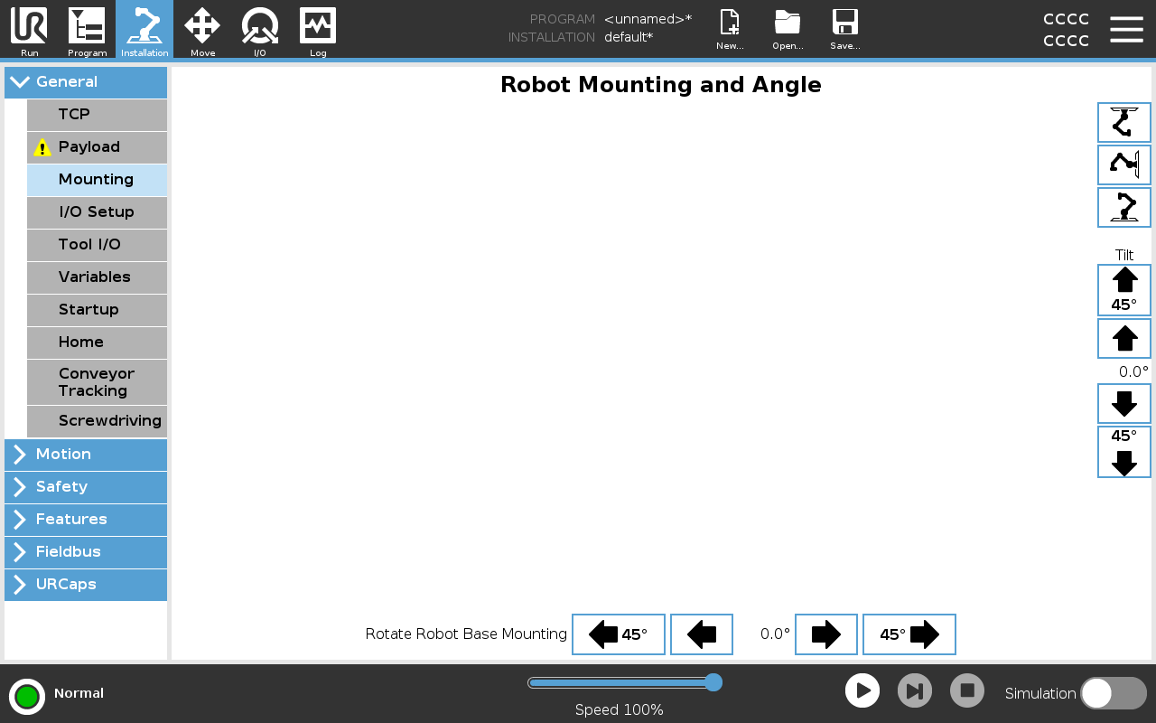
Adjusting the Robot Arm Mount
| Description |
Specifying the mounting of the robot arm serves two purposes:
Failure to mount the robot arm correctly can result in frequent stops.
Verify and use the correct installation settings. Save and load the installation files with the program.
|
|
If the robot arm is mounted in one of the ways listed below, adjustment is required.
On the Robot Mounting and Angle screen, use the buttons on the right to set the angle of the robot arm mounting. The first three buttons set the angle as follows:
The Tilt buttons set an arbitrary angle. |