Pose Editor

Description

Once you access the Pose Editor screen, you can precisely configure a target joint positions, or a target pose (position and orientation) for the TCP. Note: This screen is offline and does not control the Robot Arm directly.


Robot

The 3D image shows the current Robot Arm position. The shadow shows the Robot Arm target position controlled by the specified values on the screen. Press the magnifying glass icons to zoom in/out or drag a finger across it to change the view.
If the specified target position of the robot TCP is close to a safety or trigger plane, or the orientation of robot tool is near the tool orientation boundary limit, a 3D representation of the proximate boundary limit is shown. Safety planes are visualized in yellow and black with a small arrow representing the plane normal, which indicates the side of the plane on which the robot TCP is allowed to be positioned. Trigger planes are displayed in blue and green and a small arrow pointing to the side of the plane, where the Normal mode limits are active. The tool orientation boundary limit is visualized with a spherical cone together with a vector indicating the current orientation of the robot tool. The inside of the cone represents the allowed area for the tool orientation (vector). When the target robot TCP is no longer in proximity of the limit, the 3D representation disappears. If the target TCP is in violation or very close to violating a boundary limit, the visualization of the limit turns red.


Feature and Tool Position

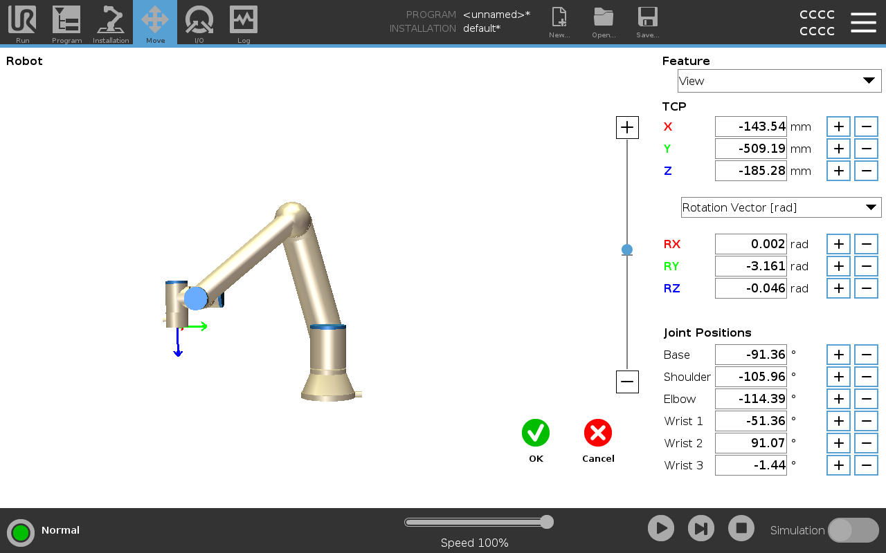
The active TCP and coordinate values of the selected feature are displayed. The X, Y, Z coordinates specify tool position. The RX, RY, RZ coordinates specify orientation. For further information about configuring several named TCPs.
Use the drop down menu above the RX, RY and RZ boxes to choose the orientation representation type:

  • Rotation Vector [rad] The orientation is given as a rotation vector. The length of the axis is the angle to be rotated in radians, and the vector itself gives the axis about which to rotate. This is the default setting.

  • Rotation Vector [] The orientation is given as a rotation vector, where the length of the vector is the angle to be rotated in degrees.

  • RPY [rad]Roll, pitch and yaw (RPY) angles, where the angles are in radians. The RPY-rotation matrix (X, Y’, Z” rotation) is given by:
    Rrpy(γ, β, α) = RZ(α) ⋅ RY(β) ⋅ RX(γ)

  • RPY []Roll, pitch and yaw (RPY) angles, where angles are in degrees.

You can tap the values to edit the coordinates. You can also tap the + or - buttons to the right of a box to add/subtract an amount to/from the current value. Or you can hold down a button to directly increase/decrease the value.


Joint Positions

Individual joint positions are specified directly. Each joint position can have Joint Limit range from  − 360 to  + 360. You can configure Joint Positions as follows:

  • Tap the joint position to edit the values.

  • Tap the + or - buttons to the right of a box to add or subtract an amount to/from the current value.

  • Hold down a button to directly increase/decrease the value.


OK Button

If you activate this screen from the Move screen, tap the OK button to return to the Move screen. The Robot Arm moves to the specified target. If the last specified value was a tool coordinate, the Robot Arm moves to the target position using movement type MoveL; or it uses movement type MoveJ if a joint position was specified last.


Cancel Button

The Cancel button exits the screen discarding all changes.