Basic Program Nodes: Move

Description

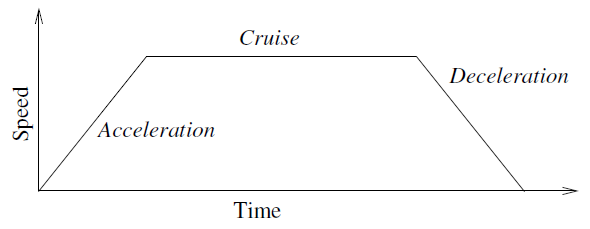
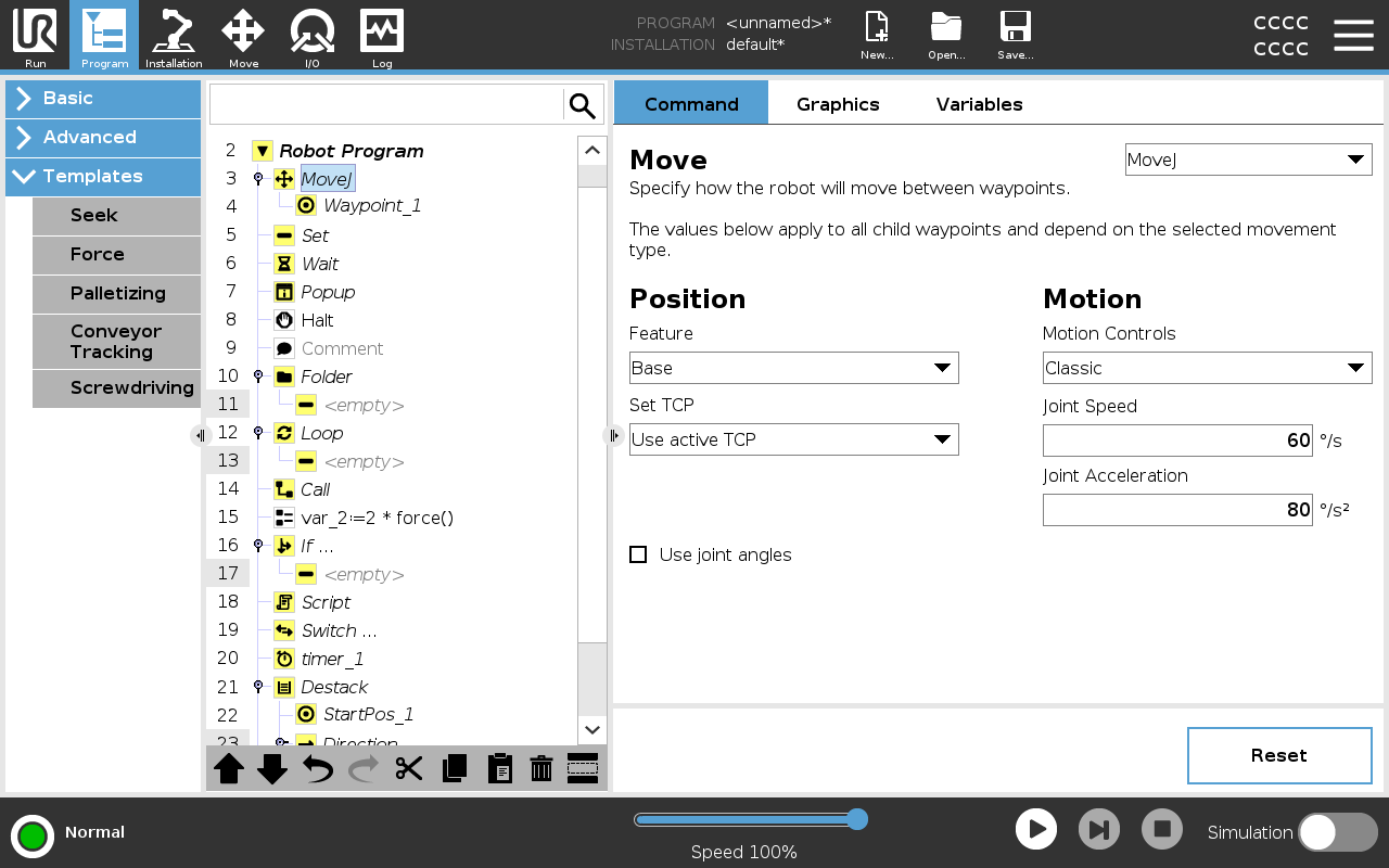
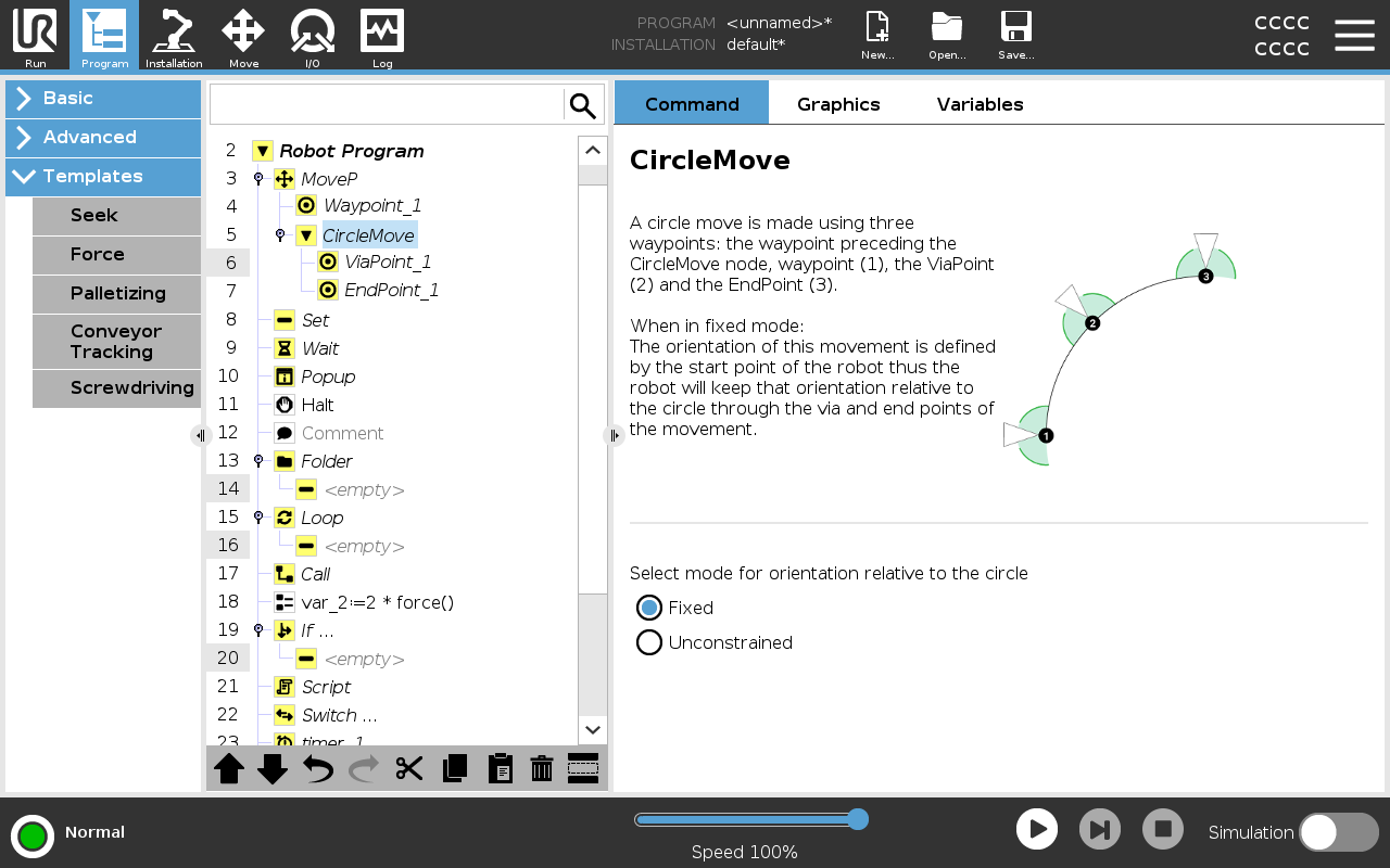
The Move command allows the robot to move from point A to point B. How the robot moves is important to the task the robot is performing. When you add a Move to your program tree, the Move pane appears to the right of the screen. The options in the Move pane allow you to configure a Move and the attached waypoint.


Speed settings


The shared parameters that apply to the movement types are the maximum joint speed and joint acceleration.

18.1:  Speed profile for a motion. The curve is divided into three segments: acceleration, cruise and deceleration. The level of the cruise phase is given by the speed setting of the motion, while the steepness of the acceleration and deceleration phases is given by the acceleration parameter.


OptiMove is a motion control option that specifies the speed and acceleration of the robot, while maintaining hardware limits. This means the optimal motion of the robot does not exceed the desired limits.

So 100% is the maximum speed percentage and acceleration within the hardware limits.


The Move command controls the robot's motion via waypoints.

Waypoints are automatically added when you add Move commands to a program.

You can also use Moves to set acceleration and speed for the robot arm's movement between waypoints.


The robot moves using four Move commands as described in the following sections:


MoveJ

The MoveJ command creates a movement from point A to point B that is optimal for the robot. The movement may not be a direct line between A and B, but optimal for the start position of the joints and the end position of the joints.

MoveJ makes movements that are calculated in the robot arm joint space. Joints are controlled to finish their movements at the same time. This movement type results in a curved path for the tool to follow.

To add a MoveJ
  1. In your robot program tree, select the place where you wish to add a Move.

  2. Under Basic, tap Move to add a Move node together with a waypoint.

  3. Select the move node.

  4. Select MoveJ in the drop-down menu.


To add a MoveJ with OptiMove
  1. In your robot program tree, select the desired move node or waypoint node.

  2. In the Motion Controls dropdown menu, select OptiMove.

  3. Use the slider to set the speed.

  4. You can select Scaled acceleration to keep the settings linked.

    You can deselect Scaled acceleration to modify the settings independently .

Using Use joint angles

The Use joint angles option is an alternative to the 3D pose when you are using MoveJ to define a waypoint.


Waypoints defined using the Use joint angle are not changed when a program is moved between robots. This is useful if you are installing your program in a new robot.


Using Use joint angles makes the TCP options and feature unavailable.


MoveL

The MoveL command creates a movement that is a direct line from point A and point B. MoveL moves the Tool Center Point (TCP) linearly between waypoints. This means that each joint performs a more complicated motion to keep the tool on a straight line path.


To add a MoveL

Adding a MoveL is similar to adding a MoveJ.

  1. In your robot program tree, select the place where you wish to add the MoveL.

  2. Under Basic, tap Move and select MoveL from the drop-down menu.

Adding a MoveL with OptiMove is also similar to adding a MoveJ with OptiMove.

Once you select the node, simply navigate to the Motion Controls dropdown and select OptiMove.


MoveP

The MoveP command creates a movement with a constant speed between the waypoints.

Blend between waypoints is enabled to ensure constant speed.

To add a MoveP

Adding a MoveP is similar to adding a MoveJ and a MoveL.

  1. In your robot program tree, select the place where you wish to add the MoveP.

  2. Under Basic, tap Move and select MoveP from the drop-down menu.

Adding a MoveP with OptiMove is also similar to adding a MoveJ with OptiMove.

Once you select the node, simply navigate to the Motion Controls dropdown and select OptiMove.

Detail

MoveP moves the tool linearly with constant speed with circular blends, and is intended for some process operations, like gluing or dispensing. The size of the blend radius is by default a shared value between all the waypoints. A smaller value will make the path turn sharper whereas a higher value will make the path smoother. While the robot arm is moving through the waypoints with constant speed, the robot control box cannot wait for either an I/O operation or an operator action. Doing so might stop the robot arm’s motion, or cause a robot stop.


MoveCircle

The MoveCircle command creates a circular movement, by creating a half circle.

You can only add CircleMove via a MoveP command.

To add a MoveCircle
  1. In your robot program tree, select the place where you wish to add a Move.

  2. Under Basic, tap Move.

    A waypoint is added to the robot program together with the Move node.

  3. Select the move node.

  4. Select the MoveP from the drop-down menu.

  5. Tap Add circle move

  6. Select the orientation mode.

Detail

The robot starts the circular movement from its current position, or start point, and moves through a ViaPoint specified on the circular arc, to an EndPoint that completes the circular movement.

A mode is used to calculate tool orientation, through the circular arc.

The mode can be:

  • Fixed: only the start point is used to define the tool orientation.

  • Unconstrained: the start point transforms to the EndPoint to define tool orientation.


Using Set TCP

Use this setting, if you need to change TCP during the robot program execution. This is useful if you need to manipulate different objects in the robot program.

The way the robot moves is adjusted depending on which TCP is set as an active TCP.

Ignore Active TCP allows this movement to be adjusted in relation to the Tool Flange.

To set the TCP in a Move
  1. Access the Program Tab screen to set the TCP used for waypoints.

  2. Under Command, in the drop down menu on the right select the Move type.

  3. Under Move, select an option in the Set TCP drop down menu.

  4. Select Use active TCP or select a user defined TCP.
    You can also choose Ignore Active TCP.

Feature

You can use Feature between waypoints for the program to remember the tool coordinates.

This is useful when you are setting the waypoints (see Features).


You can use Feature in the following circumstances:

  • Feature has no effect on relative waypoints. The relative movement is always performed with respect to orientation of the Base.

  • When the robot arm moves to a variable waypoint, the Tool Center Point (TCP) is calculated as the coordinates of the variable in the space of the selected feature. Therefore, the robot arm movement for a variable waypoint changes if another feature is selected.

  • You can change a feature’s position while the program is running by assigning a pose to its corresponding variable.

Shared Parameters in a Move Command


The shared parameters in the bottom right corner of the Move screen apply to the movement from the previous position of the robot arm to the first waypoint under the command, and from there to each of the following waypoints.

The Move command settings do not apply to the path going from the last waypoint under that Move command.