Software Safety Restrictions


| Configuring safety planes |
|
| Copy Feature |
In Copy Feature, only Undefined and Base are available. You can reset a configured safety plane by selecting Undefined If the copied feature is modified in the Features screen, a warning icon appears to the right of the Copy Feature text. This indicates that the feature is out of sync i.e. the information in the properties card is not updated to reflect the modifications that may have been made to the Feature.
|

| Color Codes |
|

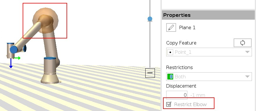
| Elbow Restriction |
You can enable Restrict Elbow to prevent robot elbow joint from passing through any of your defined planes. Disable Restrict Elbow for elbow to pass through planes. The diameter of the ball that restricts the elbow is different for each size of robot.
The information about the specific radius can be found in the urcontrol.conf file on the robot under the section [Elbow].
|
| Tool Flange Restriction |
Restricting the tool flange prevents the tool flange and the attached tool from crossing a safety plane. When you restrict the tool flange, the unrestricted area is the area inside of the safety plane, where the tool flange can operate normally. The tool flange cannot cross the restricted area, outside of the safety plane.
Removing the restriction allows the tool flange to go beyond the safety plane, to the restricted area, while the attached tool remains inside of the safety plane.
You can remove the tool flange restriction when working with a large tool off-set. This will allow extra distance for the tool to move.
Restricting the tool flange requires the creation of a plane feature. The plane feature is used to set up a safety plane later in the safety settings.
|
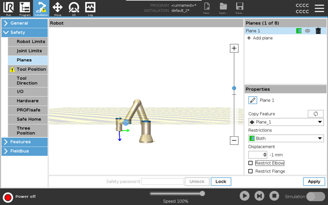
| Adding a plane feature example |
Displacement offsets the plane in either the positive or negative direction along the plane normal (Z-axis of the plane feature). Deselect the checkbox for the Elbow and the Tool Flange so they do not trigger the safety plane. The Elbow can remain checked as needed by your application.
The unrestricted tool flange can cross a safety plane, even when no tool is defined. If no tool is added, a warning on the Tool Position button prompts you to correctly define the tool. When working with an unrestricted tool flange and a defined tool, it is ensured that the dangerous part of the tool can't go above and/or beyond certain area. The unrestricted tool flange can be used for any application where safety planes are needed, like Welding or Assembly.
|
| Tool flange restriction example |
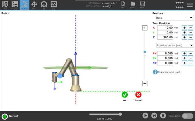
In this example, an X-Y-plane is created with an offset of 300mm along the positive Z-axis with reference to the base feature. The Z-axis of the plane can be thought of as “pointing” towards the restricted area. If the safety plane is needed on e.g., the surface of a table, rotate the plane 3.142 rad or 180° around either the X- or Y-axis so the restricted area is under the table. (TIP: Change the display of rotation from “Rotation Vector [rad]” to “RPY [°]”)
If needed it is possible to offset the plane in either positive or negative Z-direction later in the safety settings. When satisfied with the position of the plane, tap OK.
|