Force

Description

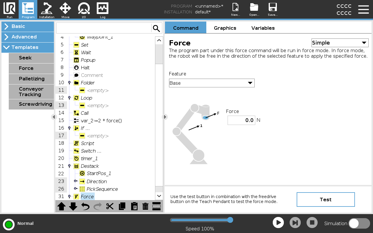
Force mode is suited to applications where the actual TCP position along a predefined axis is not important, but instead a desired force along that axis is required. For example, if the robot TCP rolls against a curved surface, pushes or pulls a workpiece.


Force mode also supports applying certain torques around predefined axes. The robot arm attempts to accelerate along that axis, if no obstacles are met in an axis where a non-zero force is set. Although an axis is selected to be compliant, the robot program still tries to move the robot along that axis. However, force control assures that the robot arm still approaches the specified force.

Using this function at the same time as Conveyor Tracking and/or Path Offset can lead to program conflict.

  • Do not use this function together with Conveyor Tracking or Path Offset.
If there is a Force node inside an If, ElseIf or Loop, and the Check Expression Continuously option is selected, you can add an end_force_mode() script at the end of the expression to exit force control.
 
  1. Avoid high deceleration just before entering force mode.

  2. Avoid high acceleration in force mode, since it decreases force control accuracy.

  3. Avoid movements parallel to compliant axes before entering force mode.


Feature selection

The Feature menu is used to select the coordinate system (axes) the robot will use while it is operating in force mode. The features in the menu are those which have been defined in the installation.


Force mode type

The types of force mode, listed below, determine how the selected feature is interpreted.

  • Simple: Only one axis will be compliant in force mode. The force along this axis is adjustable. The desired force will always be applied along the z-axis of the selected feature. However, for Line features, it is along their y-axis.

  • Frame: The Frame type allows for more advanced usage. Here, compliance and forces in all six degrees of freedom can be independently selected.

  • Point: When Point is selected, the task frame has the y-axis pointing from the robot TCP towards the origin of the selected feature. The distance between the robot TCP and the origin of the selected feature is required to be at least 10 mm. The task frame changes at runtime as the position of the robot TCP changes. The x- and z-axis of the task frame are dependent on the original orientation of the selected feature.

  • Motion: Motion means that the task frame will change with the direction of the TCP motion. The x-axis of the task frame will be the projection of the TCP movement direction onto the plane spanned by the x- and y-axis of the selected feature. The y-axis will be perpendicular to the robot arm’s motion, and in the x-y plane of the selected feature. This can be useful when de-burring along a complex path, where a force is needed perpendicular to the TCP motion.

    When the robot arm is not moving: If force mode is entered with the robot arm standing still, there will be no compliant axes until the TCP speed is above zero. If later, while still in force mode, the robot arm is again standing still, the task frame has the same orientation as the last time the TCP speed was larger than zero.

For the last three types, the actual task frame can be viewed at runtime on the graphics tab (see ), when the robot is operating in force mode.


Force value selection
  • Force or torque value can be set for compliant axes, and robot arm adjusts its position to achieve the selected force.

  • For non-compliant axes robot arm will follow the trajectory set by the program.

For translational parameters, the force is specified in Newtons [N] and for rotational the torque is specified in Newton meters [Nm].

You must do the following:

  • Use get_tcp_force() script function in separate thread, to read actual force and torque.

  • Correct wrench vector, if actual force and/or torque is lower than requested.


Speed limits

Maximum Cartesian speed can be set for compliant axes. The robot moves at this speed in force control, as long as it does not come into contact with an object.


Test force settings

The on/off button, labelled Test, toggles the behavior of the Freedrive button on the back of the Teach Pendant from normal Freedrive mode to testing the force command.

When the Test button is on and the Freedrive button on the back of the Teach Pendant is pressed, the robot will perform as if the program had reached this force command, and this way the settings can be verified before actually running the complete program. Especially, this possibility is useful for verifying that compliant axes and forces have been selected correctly. Simply hold the robot TCP using one hand and press the Freedrive button with the other, and notice in which directions the robot arm can/cannot be moved.

Upon leaving this screen, the Test button automatically switches off, which means the Freedrive button on the back of the Teach Pendant is again used for regular Freedrive mode.

The Freedrive button is only effectual when a valid feature is selected for the Force command.