Tool I/O
|
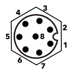
The tool connector illustrated below provides power and control signals for the grippers and sensors used on a specific robot tool. The tool connector has eight holes and is located next to the tool flange on Wrist 3. The eight wires inside the connector have different functions, as listed in the table:
The Tool Connector must be manually tightened up to a maximum of 0.4 Nm.
|
| Tool I/O Accessories |
The UR20 tool I/O can require an accessory element to facilitate connection with tools. Depending on the tool, you can use the following tool I/O accessories: Tool Flange Adapter (see Mechanical Interface) and/or Tool Cable Adapter.
|
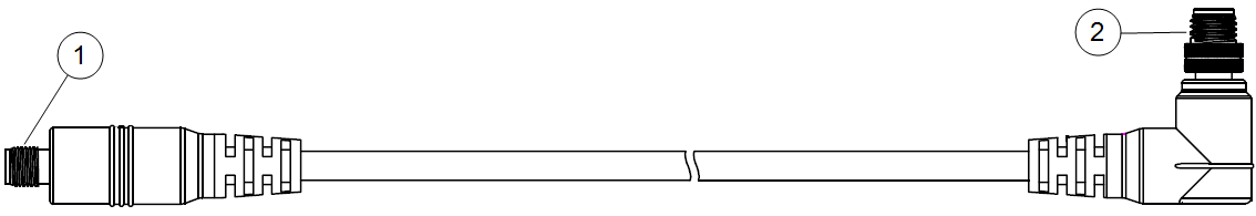
| Tool Cable Adapter |
The Tool Cable Adapter is the electronic accessory that allows compatibility between the tool I/O and e-Series tools.
Connecting the Tool Cable Adapter to a robot that is powered on can lead to injury.
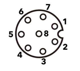
The eight wires inside the Tool Cable Adapter have different functions, as listed in the table below:
The tool flange is connected to GND (Ground).
|