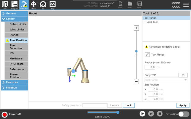
Tool Position Restriction
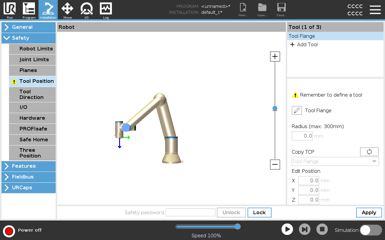
| Tool Position Warning |
You must set a Tool Position within the safety settings, for the safety plane to trigger correctly when the tool TCP approaches the safety plane. The warning remains on the Tool Position if:
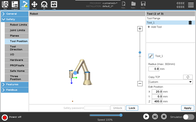
To configure the tool position
|
| Tool Position Warning example |
In this example, a Radius of 0.8mm is set and the TCP position to XYZ [20, 0, 400] in millimeters respectively. Optionally you can choose to ”Copy TCP” by using the drop-down menu if one has already been set in the ->General/TCP settings. Once the Apply is tapped in the bottom right corner of the screen, you are DONE.
The warning on the Tool Position button indicates a tool is not added under Tool Flange.
Tool Position button without the warning indicates a tool (other than the Tool Flange) is added.
|