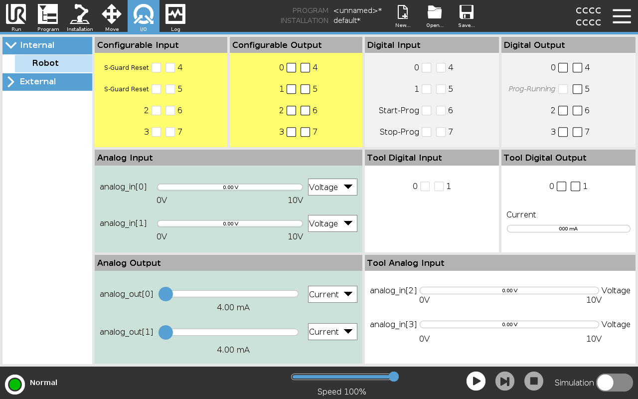
I/O Tab

Description

Use the I/O Tab screen to monitor and set the live I/O signals from/to the Control Box.


The screen displays the current state of the I/O, including during program execution. The program stops if anything is changed during execution. At program stop, all output signals retain their states. The screen updates at 10Hz, so a very fast signal might not display properly.


Configurable I/Os can be reserved for special safety settings defined in the safety I/O configuration section of the installation (see I/O); those which are reserved will have the name of the safety function in place of the default or user defined name.

Configurable outputs that are reserved for safety settings are not togglable and will be displayed as LED’s only.


Voltage

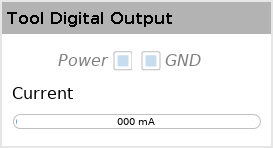
When the Tool Output is controlled by the user, you can configure Voltage. Selecting a URCap removes access to Voltage.


Analog Domain Settings

The analog I/O’s can be set to either current [4-20mA] or voltage [0-10V] output. These settings are persistent over restarts of the robot controller and saved in the installation.
Control over the tool I/Os could be assigned to a URCap in Tool I/O of the Installation tab. Selecting a URCap removes user’s control over tool’s analog I/O.


Tool Communication Interface

When the Tool Communication Interface TCI is enabled, the tool analog input becomes unavailable. On the I/O screen, the Tool Input field appears as shown.


Dual Pin power

When Dual Pin Power is enabled, the tool digital outputs must be named as follows:

  • tool_out[0] (Power)

  • tool_out[1] (GND)