Configurable Safety Functions

Description

Universal Robots robot safety functions, as listed in the table below, are in the robot but are meant to control the robot system i.e. the robot with its attached tool/end effector. The robot safety functions are used to reduce robot system risks determined by the risk assessment. Positions and speeds are relative to the base of the robot.

Safety Function Description

Joint Position Limit

Sets upper and lower limits for the allowed joint positions.

Joint Speed Limit

Sets an upper limit for joint speed.

Safety Planes

Defines planes, in space, that limit robot position. Safety planes limit either the tool/end effector alone or both the tool/end effector and the elbow.

Tool Orientation

Defines allowable orientation limits for the tool.

Speed Limit

Limits maximum robot speed. The speed is limited at the elbow, at the tool/end effector flange, and at the center of the user-defined tool/end effector positions.

Force Limit

Limits maximum force exerted by the robot tool/end effector and elbow in clamping situations. The force is limited at the tool/end effector, elbow flange and center of the user-defined tool/end effector positions.

Momentum Limit

Limits maximum momentum of the robot.

Power Limit

Limits mechanical work performed by the robot.

Stopping Time Limit

Limits maximum time the robot uses for stopping after a robot stop is initiated.1

Stopping Distance Limit

Limits maximum distance travelled by the robot after a robot stop is initiated.


Safety Function


When performing the application risk assessment, it is necessary to take into account the motion of the robot after a stop has been initiated. In order to ease this process, the safety functions Stopping Time Limit and Stopping Distance Limit can be used.

These safety functions dynamically reduces the speed of the robot motion such that it can always be stopped within the limits. The joint position limits, the safety planes and the tool/end effector orientation limits take the expected stopping distance travel into account i.e. the robot motion will slow down before the limit is reached.

The functional safety can be summarized as:

 
Safety Function Accuracy Performance Level Category
Emergency Stop d 3
Safeguard Stop d 3

Joint Position Limit

5 ° d 3

Joint Speed Limit

1.15 °/s d 3
Safety Planes 40 mm d 3
Tool Orientation 3 ° d 3
Speed Limit 50 mm/s d 3
Force Limit 25 N d 3

Momentum Limit

3 kg m/s d 3

Power Limit

10 W d 3
Stopping Time Limit 50 ms d 3
Stopping Distance Limit 40 mm d 3
Safe Home 1.7 ° d 3


Warnings

Failure to configure the maximum speed limit can result in hazardous situations.

  • If the robot is used in manual hand-guiding applications with linear movements, the speed limit must be set to maximum 250 mm/s for the tool/end effector and elbow unless a risk assessment shows that higher speeds are acceptable. This will prevent fast movements of the robot elbow near singularities.

There are two exceptions to the force limiting function that are important when designing an application.
As the robot stretches out, the knee-joint effect can give high forces in the radial direction (away from the base) at low speeds. Similarly, the short leverage arm, when the tool/end effector is close to the base and moving around the base, can cause high forces at low speeds.
Workspace

Front

Tilted


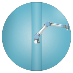
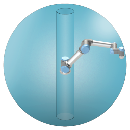
Due to the physical properties of the robot arm, certain workspace areas require attention regarding pinching hazards. One area (left) is defined for radial motions when the wrist 1 joint is at least 450 mm from the base of the robot. The other area (right) is within 200 mm of the base of the robot, when moving tangentially.


Placing the robot in certain areas can create pinching hazards that can lead to injury.


Safety inputs


The robot also has the following safety inputs:

Safety Input Description
Emergency Stop Button Performs a Stop Category 1 (IEC 60204-1) informing other machines using the System Emergency Stop output, if that output is defined. A stop is initiated in anything connected to the output.
Robot Emergency Stop Performs a Stop Category 1 (IEC 60204-1) via Control Box input, informing other machines using the System Emergency Stop output, if that output is defined.
System Emergency Stop Performs a Stop Category 1 (IEC 60204-1) on robot only, in all modes and takes precedence over all other commands.
Safeguard Stop Performs a Stop Category 2 (IEC 60204-1) in all modes, except when using a 3-Position Enabling Device and a mode selector - then when in Manual Mode, the Safeguard Stop can be set to only function in Automatic Mode.
Automatic Mode Safeguard Stop Performs a Stop Category 2 (IEC 60204-1) in Automatic mode ONLY. Automatic Mode Safeguard Stop can only be selected when a Three-Position Enabling Device is configured and installed.
Safeguard Reset Returns from the Safeguard Stop state, when a rising edge on the Safeguard Reset input occurs.
Reduced Mode Transitions the safety system to use the Reduced mode limits.
Three-Position Enabling Device Initiates a Stop Category 2 (IEC 60204-1) when the enabling device is fully pressed or fully released in manual mode only. Three-Position Enabling Device Stop is triggered when an input goes low. It is unaffected by a Safeguard Reset.
Freedrive on robot Enables freedrive, when the robot is not in Automatic Mode.
Operational Mode Switches between Operational modes. The robot is in Automatic mode when input is low, Manual mode when input is high.
Automatic Mode Safeguard Reset Returns from the Automatic Mode Safeguard Stop state, when a rising edge on the Automatic Mode Safeguard Reset input occurs.


Safety outputs

For interfacing with other machines, the robot is equipped with the following safety outputs:

Safety Output Description
System Emergency Stop While this signal is logic low, the Robot Emergency Stop input is logic low or the Emergency Stop button is pressed.
Robot Moving While this signal is logic high, no single joint of the robot moves more than 0.1 rad/s.
Robot Not Stopping Logic high when the robot is stopped or in the process of stopping due to an Emergency Stop or Safeguard Stop. Otherwise it will be logic low.
Reduced Logic low when the safety system is in Reduced Mode.
Not Reduced Logic low when the system is not in Reduced Mode.
Safe Home Logic high when robot is in the configured Safe Home Position.


All safety I/O are dual channel, meaning they are safe when low (e.g., the Emergency Stop is active when the signals are low).