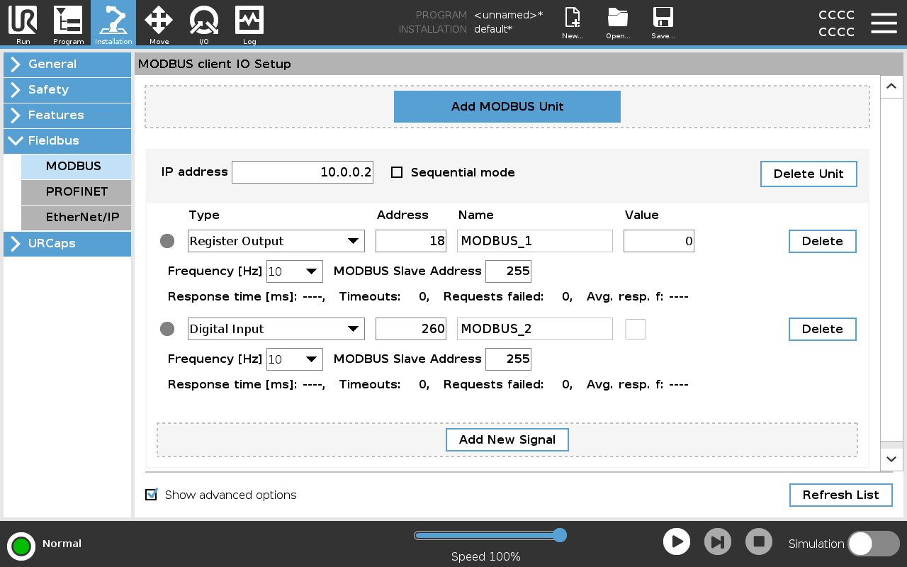
MODBUS

Description

Here, the MODBUS client (master) signals can be set up. Connections to MODBUS servers (or slaves) on specified IP addresses can be created with input/output signals (registers or digital). Each signal has a unique name so it can be used in programs.


Refresh

Push this button to refresh all MODBUS connections. Refreshing disconnects all modbus units, and connects them back again. All statistics are cleared.


Add unit

Push this button to add a new MODBUS unit.


Delete unit

Push this button to delete the MODBUS unit and all signals on that unit.


Set unit IP

Here the IP address of the MODBUS unit is shown. Press the button to change it.


Sequential mode

Available only when Show Advanced Options selected. Selecting this checkbox forces the modbus client to wait for a response before sending the next request. This mode is required by some fieldbus units. Turning this option on may help when there are multiple signals, and increasing request frequency results in signal disconnects.

The actual signal frequency may be lower than requested when multiple signals are defined in sequential mode. Actual signal frequency can be observed in signal statistics. The signal indicator turns yellow if the actual signal frequency is less than half of the value selected from the Frequency drop-down list.


Add signal

Push this button to add a signal to the corresponding MODBUS unit.


Delete signal

Push this button to delete a MODBUS signal from the corresponding MODBUS unit.


Set signal type

Use this drop down menu to choose the signal type.

Available types are:

Digital input
A digital input (coil) is a one-bit quantity which is read from the MODBUS unit on the coil specified in the address field of the signal. Function code 0x02 (Read Discrete Inputs) is used.
Digital output
A digital output (coil) is a one-bit quantity which can be set to either high or low. Before the value of this output has been set by the user, the value is read from the remote MODBUS unit. This means that function code 0x01 (Read Coils) is used. When the output has been set by a robot program or by pressing the set signal value button, the function code 0x05 (Write Single Coil) is used onwards.
Register input
A register input is a 16-bit quantity read from the address specified in the address field. The function code 0x04 (Read Input Registers) is used.
Register output

A register output is a 16-bit quantity which can be set by the user. Before the value of the register has been set, the value of it is read from the remote MODBUS unit. This means that function code 0x03 (Read Holding Registers) is used. When the output has been set by a robot program or by specifying a signal value in the set signal value field, function code 0x06 (Write Single Register) is used to set the value on the remote MODBUS unit.


Set signal address

This field shows the address on the remote MODBUS server. Use the on-screen keypad to choose a different address. Valid addresses depends on the manufacturer and configuration of the remote MODBUS unit.


Set signal name

Using the on-screen keyboard, the user can give the signal a name. This name is used when the signal is used in programs.


Signal value

Here, the current value of the signal is shown. For register signals, the value is expressed as an unsigned integer. For output signals, the desired signal value can be set using the button. Again, for a register output, the value to write to the unit must be supplied as an unsigned integer.


Signal connectivity status

This icon shows whether the signal can be properly read/written (green), or if the unit responds unexpected or is not reachable (gray). If a MODBUS exception response is received, the response code is displayed. The MODBUS-TCP Exception responses are:

E1
ILLEGAL FUNCTION (0x01) The function code received in the query is not an allowable action for the server (or slave).
E2
ILLEGAL DATA ADDRESS (0x02) The function code received in the query is not an allowable action for the server (or slave), check that the entered signal address corresponds to the setup of the remote MODBUS server.
E3
ILLEGAL DATA VALUE (0x03) A value contained in the query data field is not an allowable value for server (or slave), check that the entered signal value is valid for the specified address on the remote MODBUS server.
E4
SLAVE DEVICE FAILURE (0x04) An unrecoverable error occurred while the server (or slave) was attempting to perform the requested action.
E5
ACKNOWLEDGE (0x05) Specialized use in conjunction with programming commands sent to the remote MODBUS unit.
E6

SLAVE DEVICE BUSY (0x06) Specialized use in conjunction with programming commands sent to the remote MODBUS unit, the slave (server) is not able to respond now.


Show Advanced Options

This check box shows/hides the advanced options for each signal.


Advanced Options
Update Frequency
This menu can be used to change the update frequency of the signal. This means the frequency with which requests are sent to the remote MODBUS unit for either reading or writing the signal value. When the frequency is set to 0, then modbus requests are initiated on demand using a modbus_get_signal_status, modbus_set_output_register, and modbus_set_output_signal script functions.
Slave Address
This text field can be used to set a specific slave address for the requests corresponding to a specific signal. The value must be in the range 0-255 both included, and the default is 255. If you change this value, it is recommended to consult the manual of the remote MODBUS device to verify its functionality when changing slave address.
Reconnect count
Number of times TCP connection was closed, and connected again.
Connection status
TCP connection status.
Response time [ms]
Time between modbus request sent, and response received - this is updated only when communication is active.
Modbus packet errors
Number of received packets that contained errors (i.e. invalid length, missing data, TCP socket error).
Timeouts
Number of modbus requests that didn’t get response.
Requests failed
Number of packets that could not be sent due to invalid socket status.
Actual freq.

The average frequency of client (master) signal status updates. This value is recalculated each time the signal receives a response from the server (or slave).

All counters count up to 65535, and then wrap back to 0.