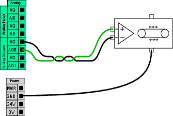
General Purpose Analog I/O

Description

The analog I/O interface is the green terminal. It is used to set or measure voltage (0-10V) or current (4-20mA) to and from other equipment.

The following directions is recommended to achieve the highest accuracy.

  • Use the AG terminal closest to the I/O. The pair share a common mode filter.

  • Use the same GND (0V) for equipment and Control Box. The analog I/O is not galvanically isolated from the Control Box.

  • Use a shielded cable or twisted pairs. Connect the shield to the GND terminal at the terminal called Power.

  • Use equipment that works in current mode. Current signals are less sensitive to interferences.


Electrical Specifications

In the GUI you can select input modes (see part Part II Software Manual). The electrical specifications are shown below.

Terminals Parameter Min Typ Max Unit
Analog Input in current mode


[AIx - AG] Current 4 - 20 mA
[AIx - AG] Resistance - 20 - ohm
[AIx - AG] Resolution - 12 - bit
Analog Input in voltage mode


[AIx - AG] Voltage 0 - 10 V
[AIx - AG] Resistance - 10 - Kohm
[AIx - AG] Resolution - 12 - bit
Analog Output in current mode


[AOx - AG] Current 4 - 20 mA
[AOx - AG] Voltage 0 - 24 V
[AOx - AG] Resolution - 12 - bit
Analog Output in voltage mode


[AOx - AG] Voltage 0 - 10 V
[AOx - AG] Current -20 - 20 mA
[AOx - AG] Resistance - 1 - ohm
[AOx - AG] Resolution - 12 - bit


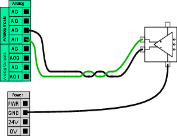
Analog Output and Analog Input


This example illustrates controlling a conveyor belt with an analog speed control input.

This example illustrates connecting an analog sensor.