Safety I/O Signals

Description

The I/O are divided between inputs and outputs and are paired up so that each function provides a Category 3 PLd capability.

Figure 1.2:  PolyScope X screen displaying the Input signals.

Input Signals

The inputs are described in the tables below:

Emergency Stop Button Performs a Stop Category 1 (IEC 60204-1) informing other machines using the System Stop output if that output is defined. A stop is initiated in anything connected to the output.
Robot Emergency Stop Performs a Stop Category 1 (IEC 60204-1) via Control Box input, informing other machines using the System Emergency Stop Output if that output is defined.
External Emergency Stop Performs a Stop Category 1 (IEC 60204-1) on robot only.
Reduced

All safety limits can be applied while the robot is using a Normal configuration, or a Reduced configuration.

When configured, a low signal sent to the inputs causes the safety system to transition to the reduced configuration. The robot arm decelerates to satisfy the reduced parameters.

The safety system guarantees the robot is within reduced limits less than 0.5s after the input is triggered. If the robot arm continues to violate any of the reduced limits, a Stop Category 0 is triggered. Trigger planes can also cause a transition to the reduced configuration. The safety system transitions to the normal configuration in the same way.

Input Signals

The inputs are described in the table below

Operational Mode When an external mode selection is used it switches between Automatic Mode and Manual Mode. The robot is in Automatic mode when input is low and Manual mode when the input is high.
Safeguard Reset Returns from the Safeguard Stop state, when a rising edge on the Safeguard Reset input occurs. When a Safeguard Stop occurs, this input ensures that the Safeguard Stop state continues until a reset is triggered.
Safeguard A stop triggered by a safeguard input. Performs a Stop Category 2 (IEC 60204-1) in all modes, when triggered by a Safeguard.
Automatic Mode Safeguard Stop Performs a Stop Category 2 (IEC 60204-1) in Automatic mode ONLY. Automatic Mode Safeguard Stop can only be selected when a Three-Position Enabling Device is configured and installed.
Automatic Mode Safeguard Reset Returns from the Automatic Mode Safeguard Stop state when a rising edge on the Automatic Mode Safeguard Reset input occurs.
Freedrive on robot You can configure the Freedrive input to enable and use Freedrive without pressing the Freedrive button on a standard TP, or without having to press-and-hold any of the buttons on the 3PE TP in the light-press position.

When the default Safeguard Reset is disabled, an automatic reset happens when the safeguard no longer triggers a stop.

This can happen if a person passes though the field of the safeguard.

If a person is not detected by the safeguard and the person is exposed to hazards, automatic reset is forbidden by standards.

  • Use the external reset to ensure resetting only when a person is not exposed to hazards.

When Automatic Mode Safeguard stop is enabled, a safeguard Stop is not triggered in Manual Mode.
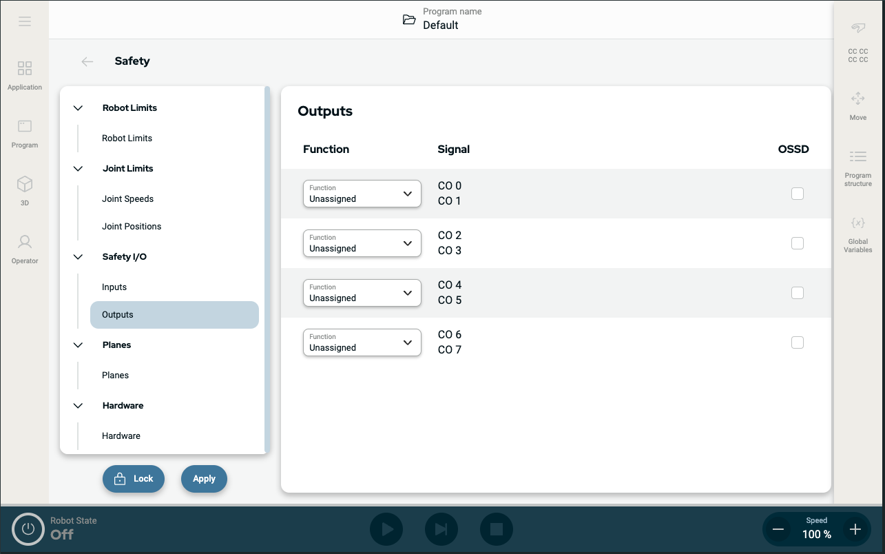
 

Output Signals

All safety outputs go low in the event of a safety system violation or fault. This means the System Stop output initiates a stop even when an E-stop is not triggered.

You can use the following Safety functions output signals. All signals return to low when the state which triggered the high signal has ended:

1System Stop Signal is Low when the safety system has been triggered into a stopped state including by the Robot Emergency Stop input or the Emergency Stop Button. To avoid deadlocks, if the Emergency Stopped state is triggered by the System Stop input, low signal will not be given.
Robot Moving Signal is Low if the robot is moving, otherwise high.
Robot Not Stopping Signal is High when the robot is stopped or in the process of stopping due to an emergency stop or safeguard stop. Otherwise it will be logic low.
Reduced Signal is Low when reduced parameters are active or if the safety input is configured with a reduced input and the signal is currently low. Otherwise the signal is high.
Not Reduced This is the inverse of Reduced, defined above.
3-Position Enabling Device In Manual Mode, an external 3-Position Enabling Device must be pressed and held in the center-on position to move the robot. If you are using a built-in 3-Position Enabling Device, the button must be pressed and held in the mid position to move the robot.
Safe Home Signal is High if the robot arm is stopped and is located in the configured Safe Home Position. Otherwise, the signal is Low. This is often used when UR robots are integrated with mobile robots.
Any external machinery receiving its Emergency Stop state from the robot through the System Stop output must comply with ISO 13850. This is particularly necessary in setups where the Robot Emergency Stop input is connected to an external Emergency Stop device. In such cases, the System Stop output becomes high when the external Emergency Stop device is released. This implies that the emergency stop state at the external machinery will be reset with no manual action needed from the robot’s operator. Hence, to comply with safety standards, the external machinery must require manual action in order to resume.