Securing the Robot Arm
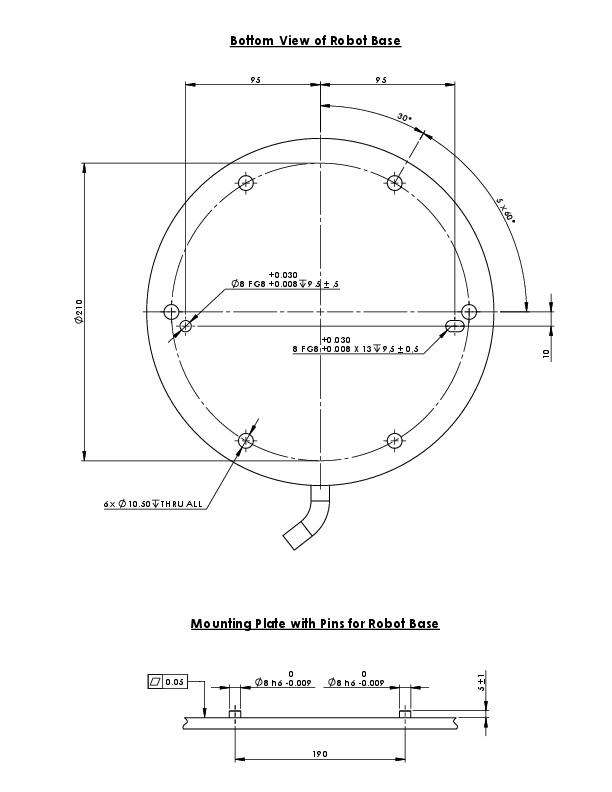
Description

Dimensions and hole pattern for mounting the robot.

To power down the robot arm

Unexpected start-up and/or movement can lead to injury

  • Power down the robot arm to prevent unexpected start-up during mounting and dismounting.

  1. Press the power button on the Teach Pendant to turn off the robot.

  2. Unplug the mains cable / power cord from the wall socket.

  3. Allow 30 seconds for the robot to discharge any stored energy.

To secure the robot arm
  1. Place the robot arm on the surface on which it is to be mounted. The surface must be even and clean.

  2. Tighten the six 8.8 strength, M10 bolts to a torque of 45 Nm.
    (Torque values have been updated SW 5.18. Earlier printed version will show different values)

  3. If accurate re-mounting of the robot is required, use the Ø8 mm. hole and Ø8x13 mm. slot with corresponding ISO 2338 Ø8 h6 positioning pins in the mounting plate.

Dimensioning the Stand

The structure (stand) on which the robot arm is mounted is a crucial part of the robot installation. The stand must be sturdy and free of any vibrations from external sources.


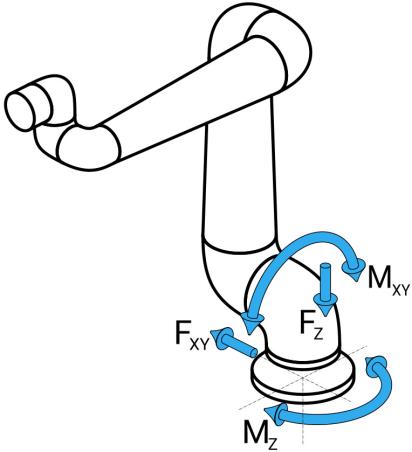
Each robot joint produces a torque that moves and stops the robot arm. During normal uninterrupted operation and during stopping motion, the joint torques are transferred to the robot stand as:

  • Mz: Torque around the base z axis.

  • Fz: Forces along base z axis.

  • Mxy: Tilting torque in any direction of the base xy plane.

  • Fxy: Force in any direction in the base xy plane.


Definition of force and moment at the base flange.

Dimensioning the Stand

The magnitude of the loads depends on robot model, program and multiple other factors.

Dimensioning of the stand shall account for the loads that the robot arm generates during normal uninterrupted operation and during category 0, 1 and 2 stopping motion. During stopping motion, the joints are allowed to exceed the maximum nominal operating torque. The load during stopping motion is independent of the stop category type.

The values stated in the following tables are maximum nominal loads in worst-case movements multiplied with a safety factor of 2.5. The actual loads will not exceed these values.

Robot Model

Mz [Nm]

Fz[Nm]

Mxy[Nm]

Fxy [Nm]

UR30

2220

3380

2950

2120

Maximum joint torques during category 0, 1 and 2 stops.

Robot Model

Mz [Nm]

Fz[Nm]

Mxy[Nm]

Fxy [Nm]

UR30

1850

2750

1890

1580

Maximum joint torques during normal operation.

The normal operating loads can generally be reduced by lowering the acceleration limits of the joints. Actual operating loads are dependent on the application and robot program. You can use URSim to evaluate the expected loads in your specific application.

Dimensioning the Stand

Users have the option to incorporate added safety margins, factoring in the following design considerations:


  • Static stiffness: A stand that is not sufficiently stiff will deflect during robot motion, resulting in the robot arm not hitting the intended waypoint or path. Lack of static stiffness can also result in a poor freedrive teaching experience or protective stops.

  • Dynamic stiffness: If the eigenfrequency of the stand matches the movement frequency of the robot arm, the entire system can resonate, creating the impression that the robot arm is vibrating. Lack of dynamic stiffness can also result in protective stops. The stand should have a minimum resonance frequency of 45 Hz.

  • Fatigue: The stand shall be dimensioned to match the expected operating lifetime and load cycles of the complete system.

  • If the robot is mounted on an external axis, the accelerations of this axis must not be too high. You can let the robot software compensate for the acceleration of external axes by using the script command set_base_acceleration()

  • High accelerations might cause the robot to make safety stops.

  • Potential for tip-over Hazards.

  • The robot arm's operational loads may cause movable platforms, such as tables or mobile robots, to tip over, resulting in possible accidents.

  • Prioritize safety by implementing adequate measures to prevent the tipping of movable platforms at all times.