Safety I/O

Safety I/O

This section describes dedicated safety input (Yellow terminal with red text) and configurable I/O (Yellow terminals with black text) when configured as safety I/O.
Safety devices and equipment must be installed according to the safety instructions and the risk assessment in chapter Safety.

All safety I/O are paired (redundant), so a single fault does not cause loss of the safety function. However, the safety I/O must be kept as two separate branches.


The permanent safety input types are:

  • Robot Emergency Stop for emergency stop equipment only

  • Safeguard Stop for protective devices

  • 3PE Stop for protective devices

Table


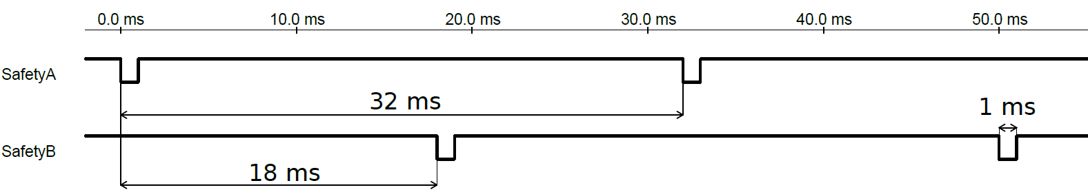
The functional difference is shown below.


Emergency Stop Safeguard Stop 3PE Stop
Robot stops moving Yes Yes Yes
Program execution Pauses Pauses Pauses
Drive power Off On On
Reset Manual Automatic or manual Automatic or manual
Frequency of use Infrequent Every cycle to infrequent Every cycle to infrequent
Requires re-initialization Brake release only No No
Stop Category (IEC 60204-1) 1 2 2
Performance level of monitoring function (ISO 13849-1) PLd PLd PLd
Safety caution


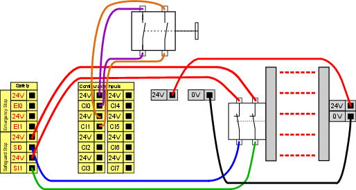
Use the configurable I/O to set up additional safety I/O functionality, e.g. Emergency Stop Output. Configuring a set of configurable I/O for safety functions are done through the GUI, (see part Part II PolyScope Manual).

Failure to verify and test the safety functions regularly can lead to hazardous situations.

  • Safety functions shall be verified before putting the robot into operation.

  • Safety functions shall be tested regularly.

OSSD signals

All configured and permanent safety inputs are filtered to allow the use of OSSD safety equipment with pulse lengths under 3ms. The safety input is sampled every millisecond and the state of the input is determined by the most frequently seen input signal over the last 7 milliseconds.


OSSD Safety Signals

You can configure the Control Box to output OSSD pulses when a safety output is inactive/high. OSSD pulses detect the ability of the Control Box to make safety outputs active/low. When OSSD pulses are enabled for an output, a 1ms low pulse is generated on the safety output once every 32ms. The safety system detects when an output is connected to a supply and shuts down the robot.

The illustration below shows: the time between pulses on a channel (32ms), the pulse length (1ms) and the time from a pulse on one channel to a pulse on the other channel (18ms)

To enable OSSD for Safety Output

  1. In the Header, tap Installation and select Safety.

  2. Under Safety, select I/O.

  3. On the I/O screen, under Output Signal, select the desired OSSD checkbox. You must assign the output signal to enable the OSSD checkboxes.


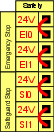
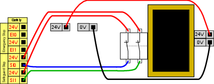
Default safety configuration

The robot is delivered with a default configuration, which enables operation without any additional safety equipment (see illustration below).


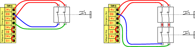
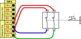
Connecting emergency stop buttons

Most applications require one or more extra emergency stop buttons. The illustration below shows how one or more emergency stop buttons can be connected.


Sharing the Emergency Stop with other machines

You can set up a shared emergency stop function between the robot and other machines by configuring the following I/O functions via the GUI. The Robot Emergency Stop Input cannot be used for sharing purposes. If more than two UR robots or other machines need to be connected, a safety PLC must be used to control the emergency stop signals.

  • Configurable input pair: External emergency stop.

  • Configurable output pair: System emergency stop.

The illustration below shows how two UR robots share their emergency stop functions. In this example the configured I/Os used are CI0-CI1 and CO0-CO1.


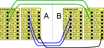
Safeguard stop with automatic resume

This configuration is only intended for applications where the operator cannot go through the door and close it behind him. The configurable I/O is used to setup a reset button outside the door to reactivate robot motion. The robot resumes movement automatically when the signal is re-established.

Do not use this configuration if signal can be re-established from the inside of the safety perimeter.

This example illustrates a door switch is a basic safeguard device where the robot is stopped when the door is opened. This example illustrates a safety mat is a safety device where automatic resume is appropriate. This example is also valid for a safety laser scanner.


Safeguard Stop with reset button

If the safeguard interface is used to interact with a light curtain, a reset outside the safety perimeter is required. The reset button must be a two channel type. In this example the I/O configured for reset is CI0-CI1 (see below).