Create Safety Plane Using a Frame
| Description |
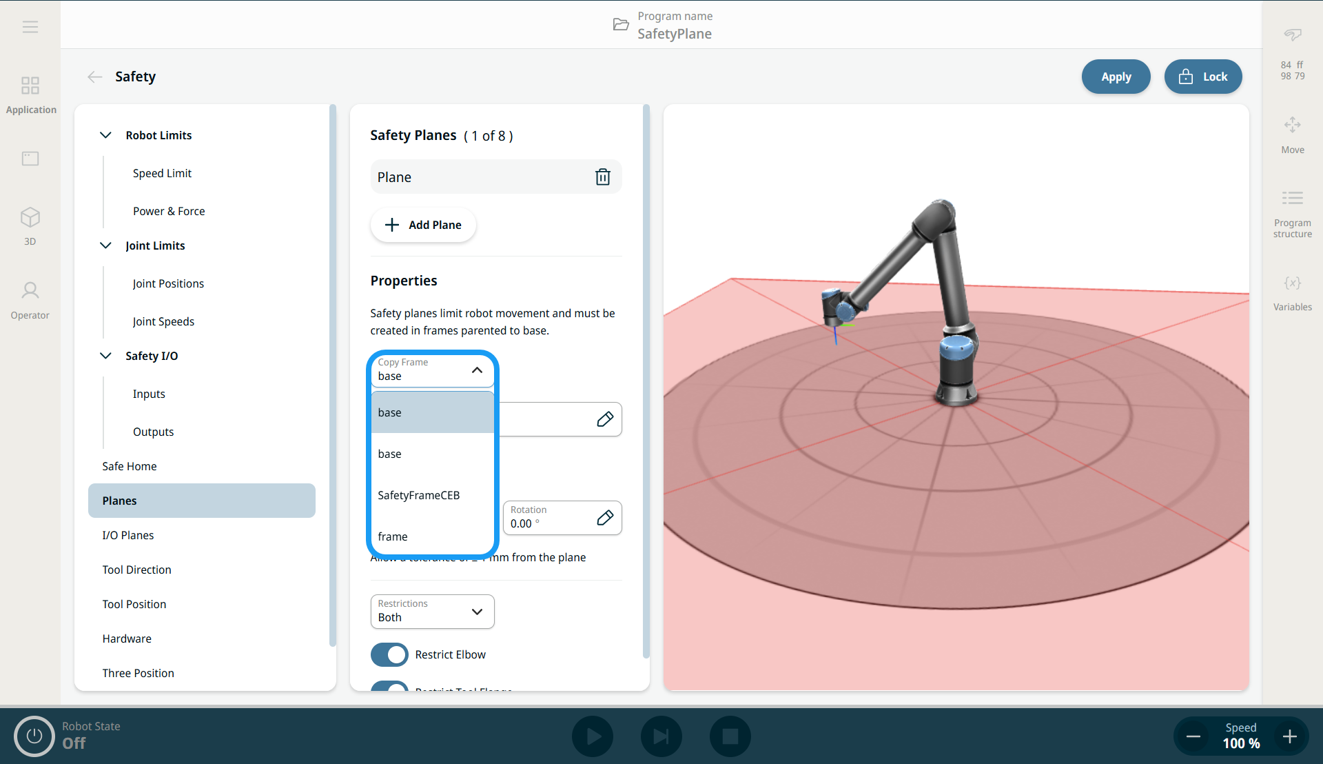
You can use an existing frame to define a safety plane. This provides a more intuitive way to specify plane parameters from a predefined position and rotation (X, Y, Z, RX, RY, RZ). Select the frame in the Copy Frame drop-down menu.
The Copy Frame drop-down menu is found in the parameters of a safety plane definition on the Planes screen. This list includes frames defined on the Frames screen. When you select a frame, it is used as the safety plane definition. If you specify offset, tilt, and rotation parameters, they are applied to the selected frame (see "Configuring a Safety Plane"). The resulting safety plane combines all parameters.
|
|
|
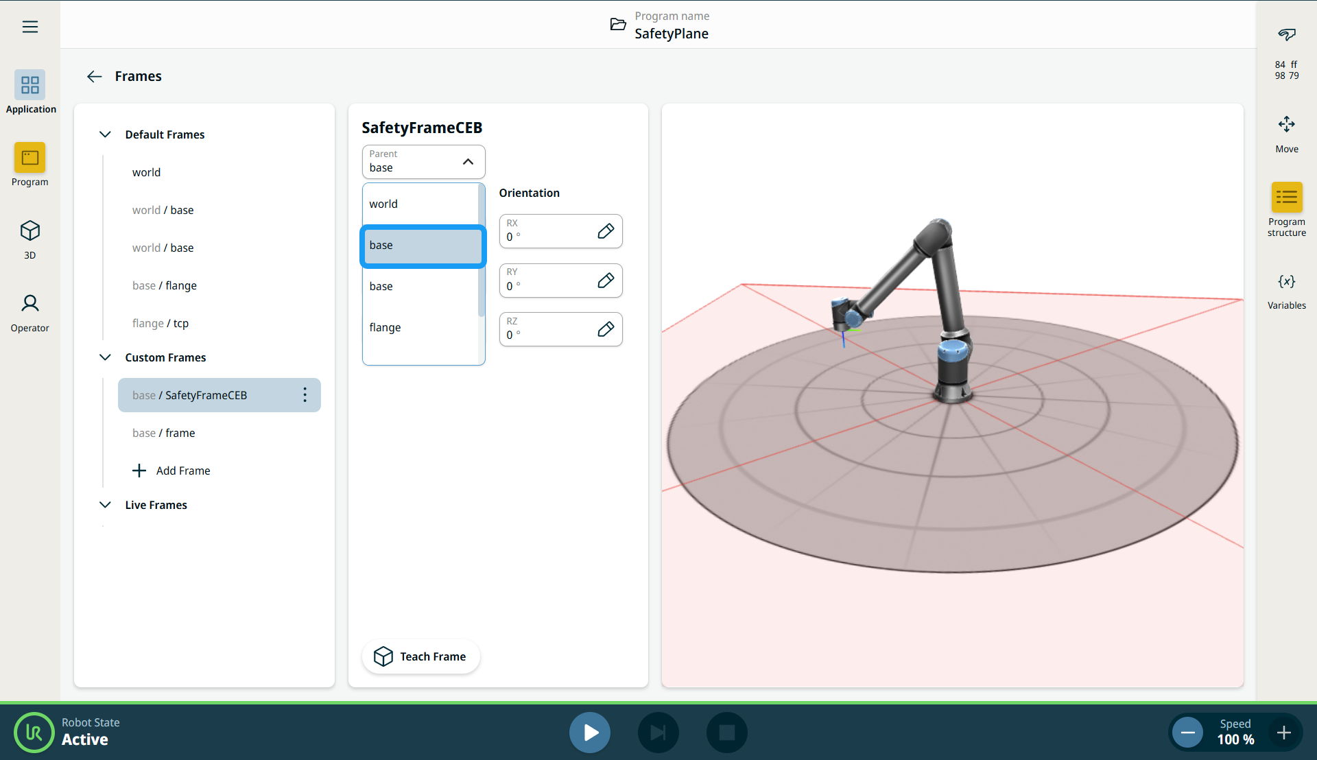
See the "Frames" section in Software Handbook. |
|
Creating Safety Planes using Frames |
|
|
|
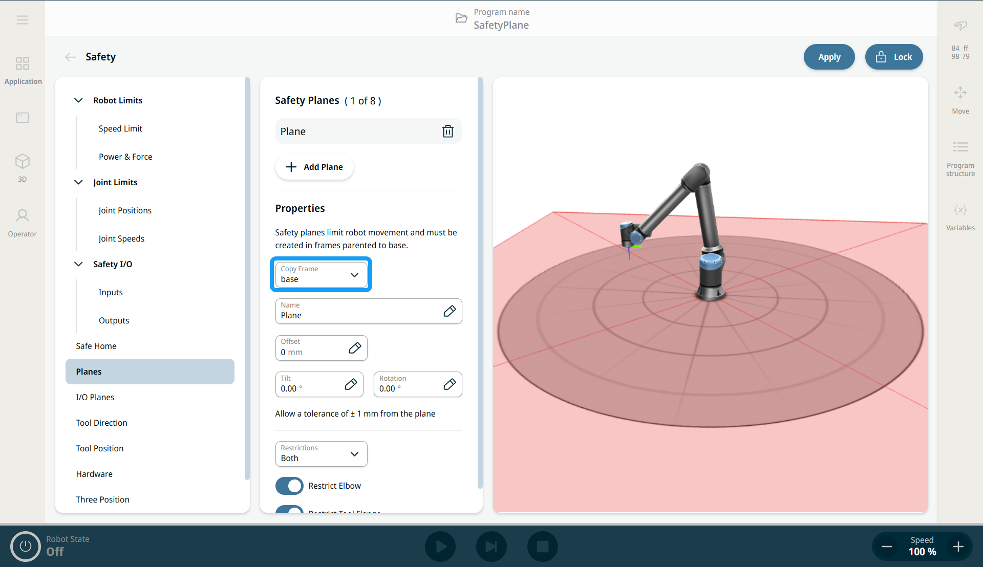
Selecting Reference Frame in Safety Plane |
|
|
|
|
|
|
A frame used for a safety plane may be inverted from what you expect. If the robot is positioned on the violating side of the plane, add a tilt of 180 degrees. For restrictions on plane configurations, elbow joint restriction, and tool flange restriction, see "Safety Planes".
|