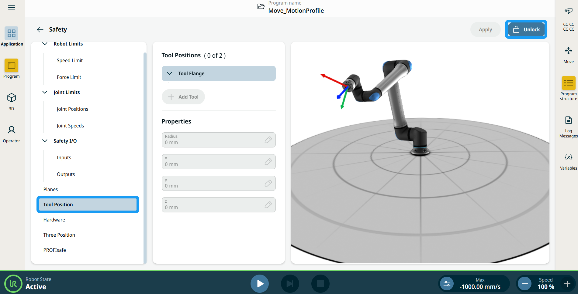
Tool Position Restriction

Description

The Tool Position screen enables users a more controlled restriction of tools and/or accessories placed on the end of the robot arm by letting you define tool positions with a radius that will interact with the safety planes by either collision detection with Tool Position and plane or enter reduced mode when tool enters plane.


Details

Tool Position has two key benefits:

  • Supports two custom configurations to specify where to react to safety planes.

  • Visualizes Tool Positions in 3D model.

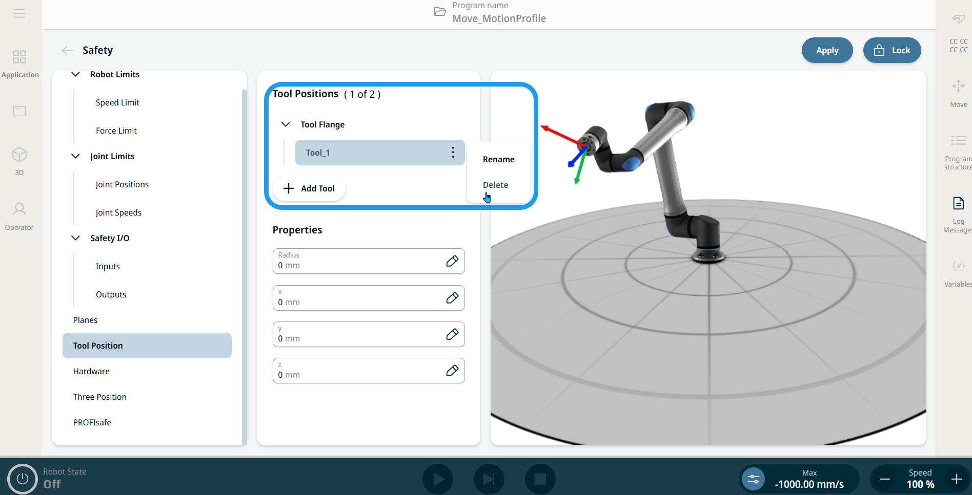
You can define, configure, and manage up to two tool positions.
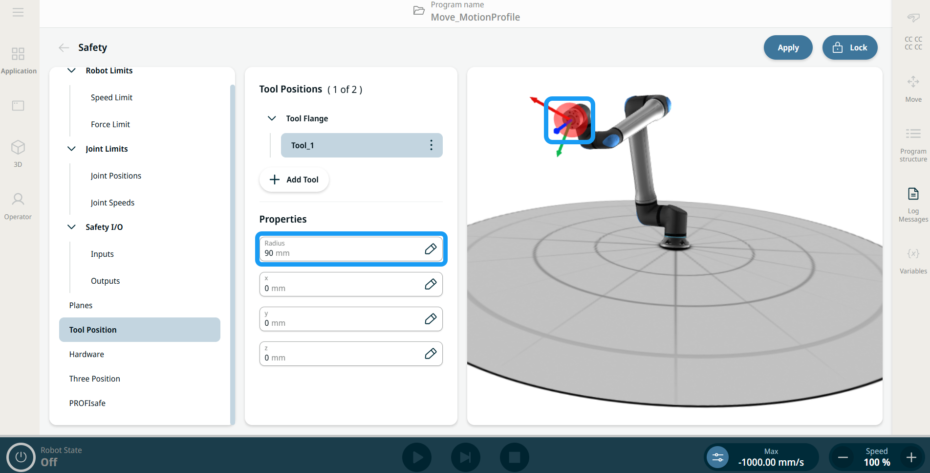


User defined tools

For the user defined tools, the user can change:

  • Radius to change the radius of the tool sphere. The radius is considered when using safety planes.

  • X, Y, Z positions to change the position of the tool with respect to the tool flange of the robot. The position is considered for the safety functions for tool speed, tool force, stopping distance, and safety planes.


To access Tool Position

  1. Navigate to Safety Application.

  2. Tap Tool Position in the left panel. On the top right side of the main screen, tap Unlock to activate adding tools. Enter the safety password and Confirm.


  1. In the central panel’s Tool Positions column, tap + Add Tool. The added tool, Tool_1, appears under the Tool Flange tree.

  2. Tap the kebab icon of the added tool to rename it to something more identifiable. You can also delete it.


  1. In the central panel’s Properties column, you can find four editable fields for radius, x, y, and z positions. Tap the fields to change the radius and x ,y, z coordinates as needed. The sphere in the right panel updates live in the 3D model to assist with accurate placement.

  2. Tap Apply in the top-right part of the main screen.


  3. The robot will now interact with safety planes when the tool position spheres come into contact with them.