|
Using the Frames application functionality
|
-
Go to the application nodes screen. See Application Tab.
-
Tap the Frames icon.
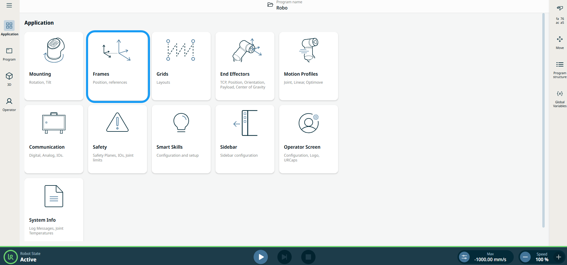
A screen appears, which is divided into three panels.
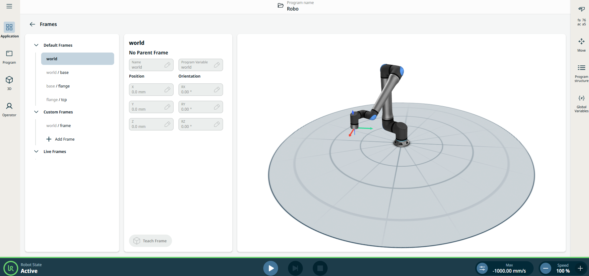
The left panel contains the Default Frames, Custom Frames, and Live Frames.
The center panel contains eight fields:
-
Name field
-
Program Variable field
-
X Position field
-
Y Position field
-
Z Position field
-
RX Orientation field
-
RY Orientation field
-
RZ Orientation field
The right column/panel shows the robot arm in X, Y, Z coordinates.
|
|
|
Under the Default Frames are found the three predefined PolyScope X frames:
-
Base. This is the center of the base of the robot. If your robot is mounted in a fixed location, this frame will never need to change, and other fixed locations can be defined relative to it.
-
TCP. This is the position of the active TCP. It will update as the robot moves when jogged or while a program is running.
-
World. When the robot is mounted in a fixed location, this frame is the same as the base. However, if your robot is mounted on a moveable rail or gantry, it is then possible to update the base frame as the robot moves, while the world frame is always fixed.
Selecting any of the predefined frames will allow you to view their values. However, they cannot be edited.
-
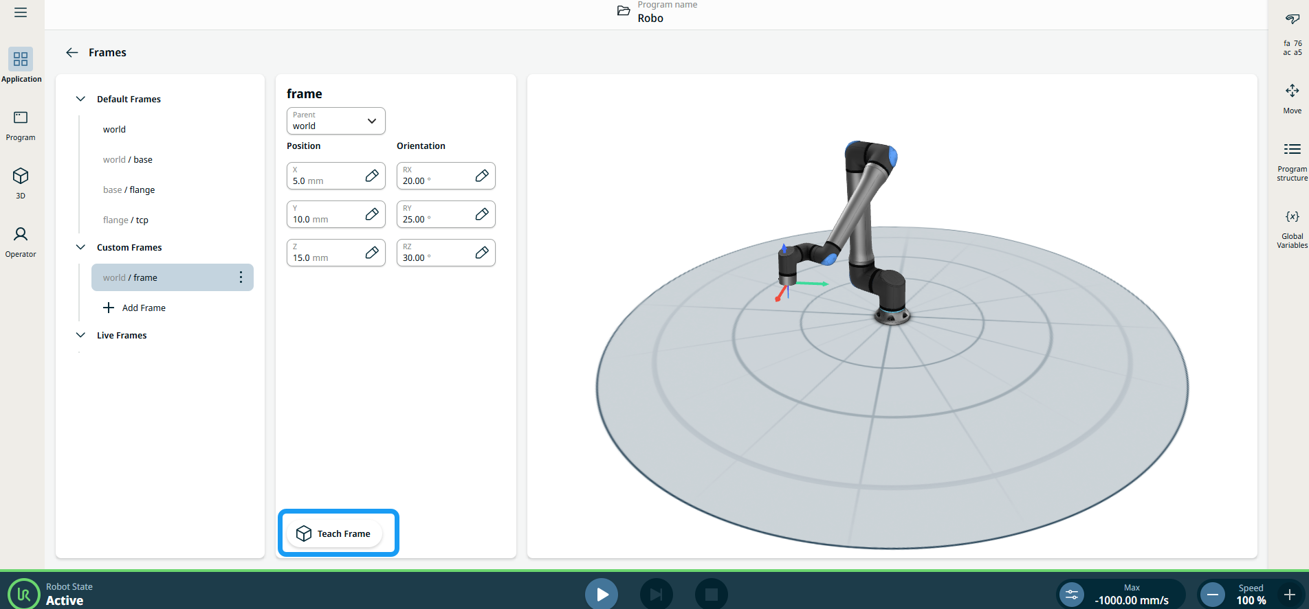
Under the Custom Frames, tap + Add frame. The eight fields in the center column/panel are activated.
-
In the Parent field, choose your frame.
-
Edit your value in the X, Y, Z Position fields and Confirm.
-
Edit your value in the RX, RY, RZ Orientation fields and Confirm.
-
Tap Teach Frame button found at the bottom of the panel.
|
| |
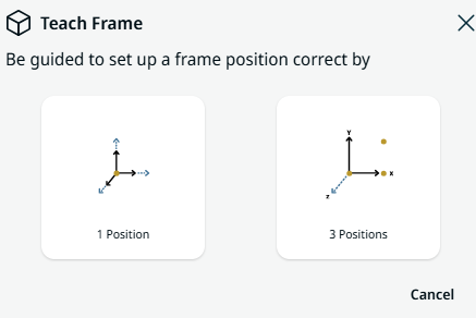
A pop-up screen appears with two options to set up a frame position.
-
1 Position
-
3 Positions
-
When you select 1 Position, the 3D viewer becomes the main screen. Use the plus-minus button to translate and rotate the robot arm's three coordinates.
-
Tap Save.
-
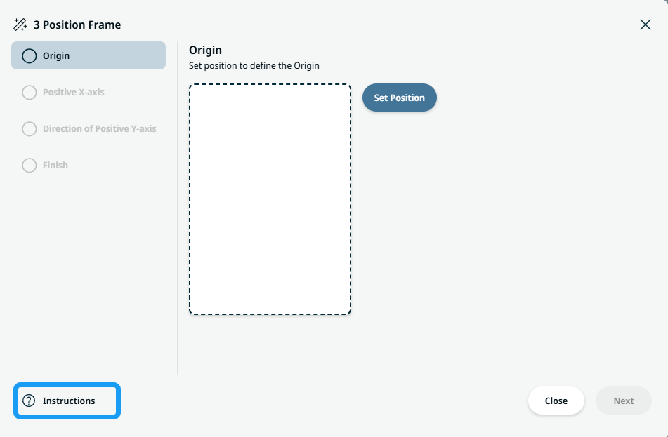
When you select 3 Positions, a pop-up screen appears. Tap the Instructions icon on the bottom left side.
|
| |
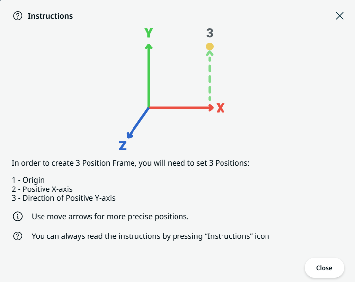
The Instructions box on how to create 3-Position Frame appears.
-
Tap Set Position for Origin.
-
The 3D viewer becomes the main screen. Use the plus-minus button to translate and rotate the robot arm's three coordinates.
-
Tap Save.
-
An option to edit position is provided. If there is no need to edit, tap Next.
-
Tap Set Position for Positive X-axis.
-
Repeat steps 12–14.
|
| |
-
Tap Set Position for Direction of Positive Y-axis.
-
Repeat steps 12–14.
-
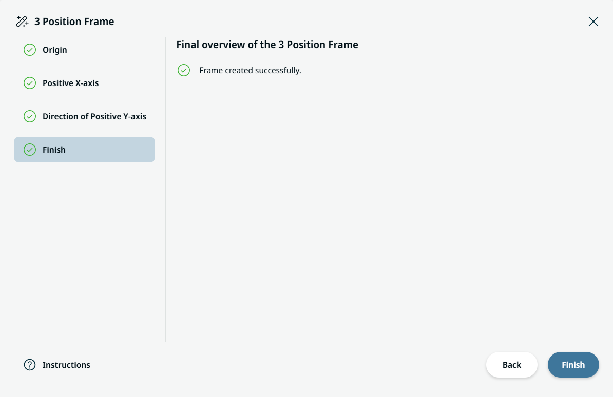
Tap Finish when frame is created successfully.
|


