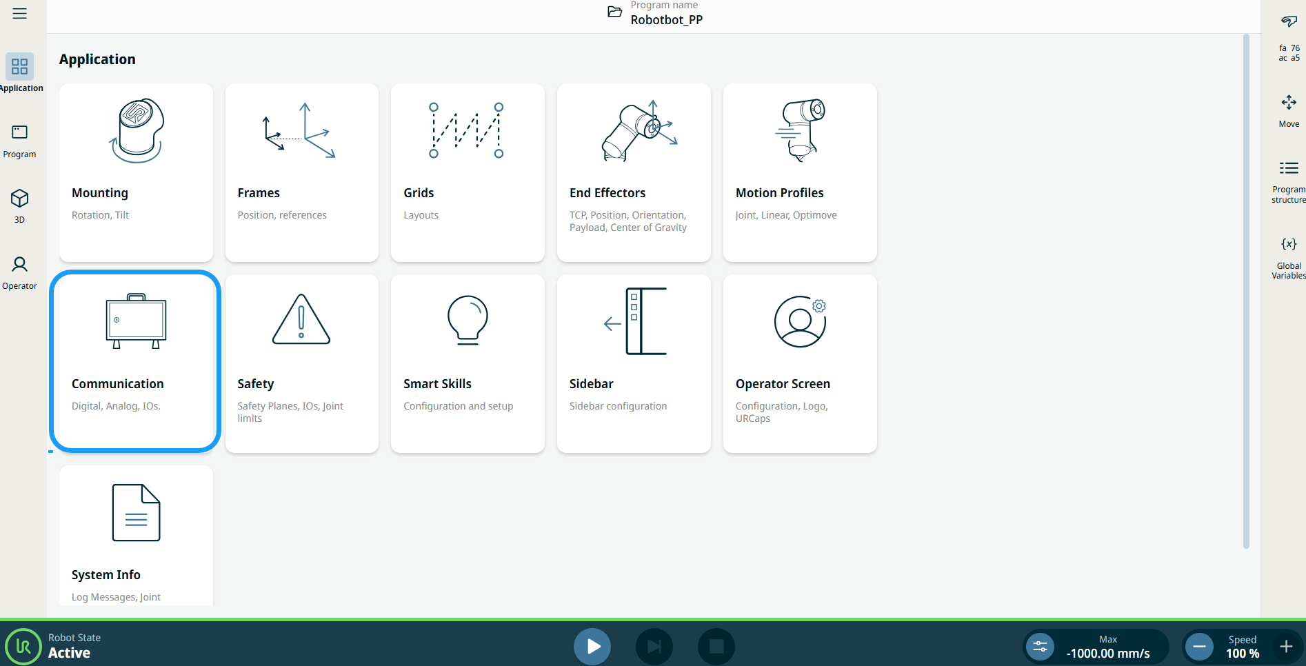
Communication

Description

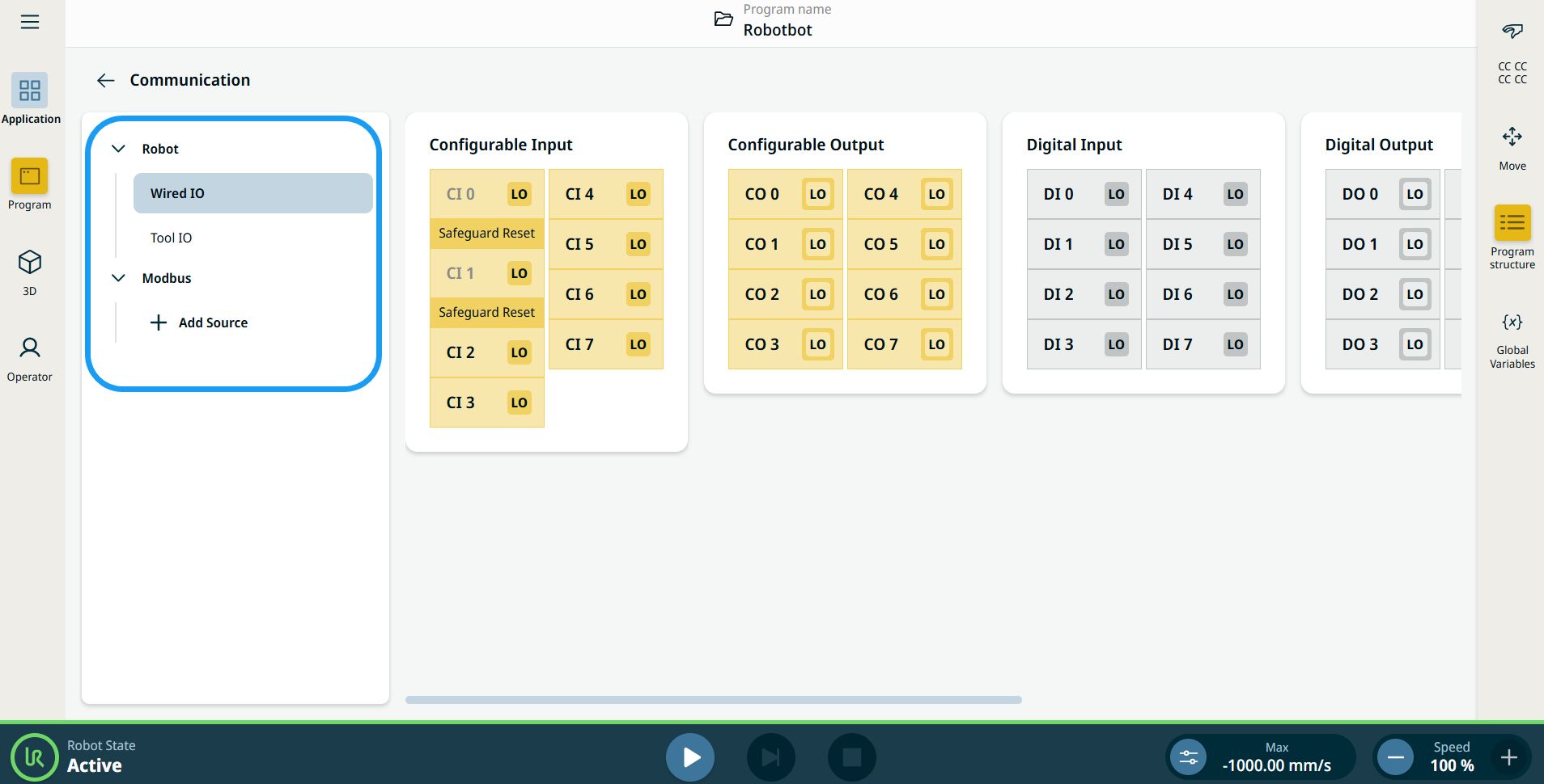
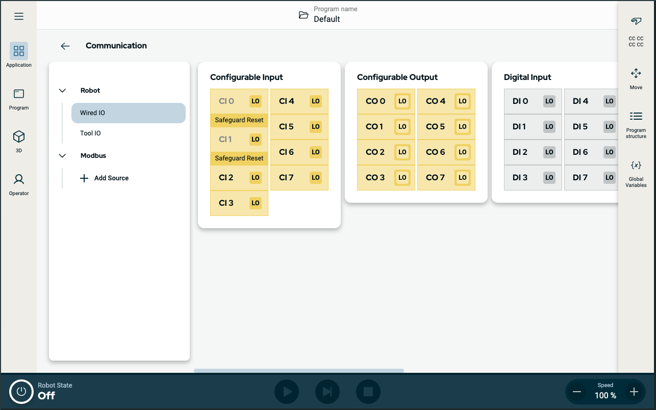
The Communication application allows you to monitor and set the live IO (input-output) signals from/to the robot control box.


Figure 1.5:  Communication screen displaying IOs.


Using the Communication application functionality

  1. Go to the Application menu screen. See Application Tab.

  2. Tap the Communication icon.


    The Communication screen appears, which is divided into the left panel and the right panels.


    The left panel consists of the communication tree, composed of three functions:

    • Robot Wired IO

      Wired IO is used to monitor and set the live IO signals from/to the control box.

    • Robot Tool IO

    • Modbus

    The right panels show the editable fields of the chosen function.

To access Wired IO

  1. Tap Wired IO on the left panel.

    The Communication screen displays the current state of the IO, including during program execution. If anything is changed during program execution, the program stops. At program stop, all output signals retain their states.

  2. Use the scrollbar on the right panel to move sideways, and you can see the editable fields of the six components of the wired IO:

    • Configurable Input

    • Configurable Output

    • Digital Input

    • Digital Output

    • Analog Input

    • Analog Output


    Input is used to start, stop, or pause the program, or as an external freedrive button.

    Output shows whether the robot is running or not.

Configurable Input

Configurable input can be reserved for special safety settings defined in the IO Setup under Safety IO. Under those which are reserved for safety settings (CI 0 and CI 1), named Safeguard Reset, are in gray and cannot be edited. CI 2–CI 7 have editable fields.

  1. Tap CI 2, and the Name and Action Preset fields appear. In the Name field, create a name and Confirm. The new name can now be seen in the communication screen.

 
  1. Tap the Action Preset field, and five choices are available:

    • None

    • Start Program. Starts the loaded program.

    • Stop Program. Stops the loaded program.

    • Pause Program. Pauses the loaded program.

    • Freedrive. Sets the robot in freedrive mode, just like the button on the back of the teach pendant.

  2. Choose the pertinent action preset.

  3. Repeat the steps above for CI 3 to CI 7.

Configurable Output

The Configurable Output field ranges from CO 0 to CO 7.

  1. You can click the square button beside each CO to choose either LO or HI.

  2. Tap CO 0, and the Name and Action Preset fields appear.

  3. In the Name field, create a name and Confirm. The new name can now be seen in the communication screen.

 
  1. Tap the Action Preset field, and nine choices are available:

    • None

    • Low when not running. Output state is LO. Program state is stopped or paused.

    • High when not running. Output state is HI. Program state is stopped or paused.

    • High when running, Low when stopped. Output state is LO then HI. Program state is running, stopped, or paused.

    • Low on unscheduled stop. Output state is LO. Program state is terminated unscheduled.

    • Low on unscheduled stop, otherwise High. Output state is LO then HI. Program state is terminated unscheduled, running, stopped, or paused.

    • Continuous Pulse. Output state alternates from LO to HI. Program state is running.

    • High when drive power is on, otherwise Low.Output state is HI.

    • Low when drive power is on, otherwise High. Output state is LO.

  2. Choose the pertinent action preset.

    By selecting the last two action presets, the HI/LO value of signals will be changed when power is OFF/ON.

Digital Input

The Digital Input field ranges from DI 0 to DI 7.

  1. Tap DI 0, and the Name and Action Preset fields appear.

  2. In the Name field, create a name and Confirm. The new name can now be seen in the communication screen.

  3. Repeat steps 3 onward of Configurable Input for DI 1 to DI 7.

Digital Output

The Digital Output field ranges from DO 0 to DO 7 and are set independently to either high or low.

Follow all the steps as in Configurable Output.

Analog Input

Analog input has two fields for AI 0 and AI 1. It can be set to 4–20 mA. These settings are persistent over restarts of the robot controller and saved in the installation.

  1. Tap AI 0. The Name and Domain fields appear.

  2. In the Name field, create the name you prefer.

  3. Tap the Domain field, and you can choose either Current or Voltage.

  4. Tap AI 1.

  5. Repeat steps 2–3.

Analog Output

Analog output has two fields for AO 0 and AO 1. As with analog input, it can be set to 4–20 mA.

  1. Tap the purple slider of each field to adjust the current or voltage settings.

  2. Tap AO 0.

  3. In the Domain field, you can choose either Current or Voltage.

  4. Tap the Action Preset field, and eight choices are available:

    • None

    • Min when not running

    • Max when not running

    • Max when running, Min when stopped

    • Min on unscheduled stop

    • Min on unscheduled stop, otherwise Max

    • Max when drive power is on, otherwise Min

    • Min when drive power is on, otherwise Max


  1. Choose the pertinent action preset. The purple slider reflects the action preset you choose.

  2. Tap AO 1 and repeat steps 3–5.

    By selecting the last two action preset, the Min/Max value of signals will be changed when power is OFF/ON.

To access Tool IO

Tool IO monitors and sets the live IO signals from/to the control box.


Tap Tool IO on the left panel. You can see the editable fields of Tool Input and Tool Output on the right.


Tool Input

The Tool Input is composed of four fields:

  • DI 0

  • DI 1

  • AI 0

  • AI 1


  1. Tap DI 0, and the Name and Action Preset fields appear.

  2. In the Name field, create a name and Confirm.

  3. Tap the Action Preset field and select from the five available choices.

  4. Repeat steps 1–3 for DI 1.

  5. Tap AI 0. A Name and Domain fields appear.

  6. In the Name field, create the name you prefer.

  7. Tap the Domain field, and you can choose either Current or Voltage.

  8. Repeat steps 5–7 for AI 1.

Tool Output

The Tool Output is composed of five fields:

  • DO 0

  • DO 1

  • Tool Output

  • Dual Pin Power

  • Power Supply

  1. You can click the square button beside each DO to choose either LO or HI.

  2. Tap DO 0, and three fields appear:

    • Name

    • Action Preset

    • Power Output

  3. In the Name field, create the name and Confirm.

  4. Tap the Action Preset field and nine choices are available.

  5. Choose the pertinent action preset.

  6. Tap the Power Output field, and four choices are available:

    • Disabled

    • Sinking (NPN). When the output is off, the pin allows a current to flow to the ground.

    • Sourcing (PNP). When the output is on, the pin provides a positive voltage source.

    • Push/Pull. When the output is on, the pin provides a positive voltage source.

  7. Choose the pertinent power output.

  8. Repeat the steps for DO 1.

  9. Tap the Tool Output field and choose among the three options available: 0 V, 12 V, 24 V.

  10. Dual Pin Power is used as a source of power for the tool. Tap to enable the Dual Pin Power. The default tool digital outputs are disabled.

Modbus

Modbus is a serial communication protocol tied to a known IP address. It holds several input/output registers.

  1. Tap + Add Source under the Modbus tree, and the communication screen shows the Modbus: Source.

  2. Tap the IP address field to edit and Confirm.

  3. Check the Sequential mode checkbox to force the Modbus client to wait for a response before sending the next request.

  4. Tap + Add Signal, and a screen appears with these editable fields:

    • Signal Name

    • Address From

    • Address To

    • Signal Type

    • Frequency

    • Timeout

    • Slave Address

 
  1. In the Signal Name field, you can edit and Confirm.

  2. Check the Address Range checkbox to activate Address To field.

  3. Enter the Address From and To respectively, and Confirm.

  1. Tap the Signal Type field, and five choices are available:

    • Read Digital Inputs

    • Read Input Registers

    • Read Holding Registers

    • Write Digital Outputs

    • Write Output Registers

  2. Choose the pertinent signal type.

  3. Tap the Frequency field and choose the pertinent frequency.

  4. Tap the Timeout field, enter the value, and Confirm.

  5. On the Slave Address field, enter the value, and Confirm.

  6. To finish, tap Add on the right bottom part of Add Signal screen.